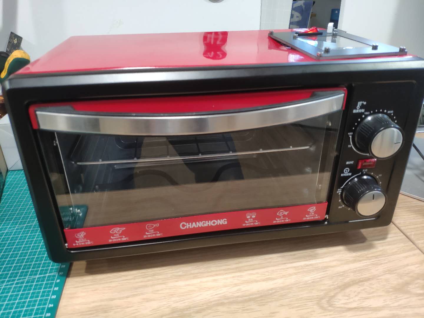
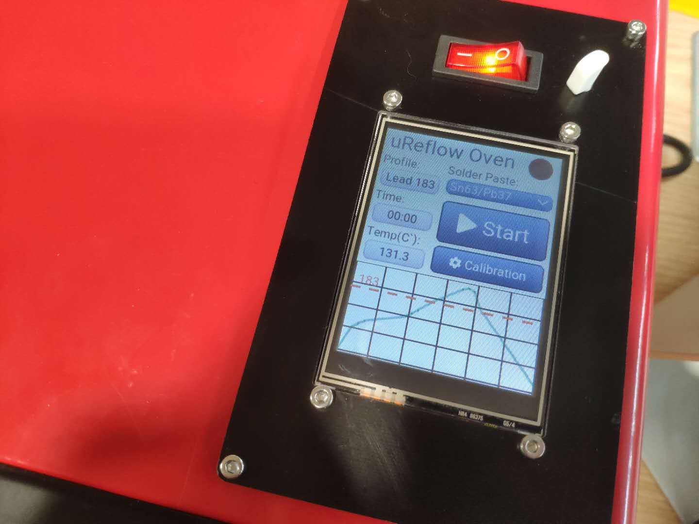
I have made a reflow oven based on ESP32 with MicroPython & Littlevgl.
Here’s the repo: https://github.com/dukeduck1984/uReflowOven-Esp32-Micropython
I have made a reflow oven based on ESP32 with MicroPython & Littlevgl.
Here’s the repo: https://github.com/dukeduck1984/uReflowOven-Esp32-Micropython
Very nice job!
Nice graph, I assume it is using LVGL v6, if so, are you planning to update it once v7 becomes stable?
I didn’t pay attention to the version of the LVGL when I built the firmware from lv_micropython repo. I don’t plan to update the GUI as long as it works. However I will probably rewrite the temperature control logic when I have time.
Sounds fair, I need a reflow oven myself, I will check your repo and try to reproduce it 
How are the remaining pins of the touch controller to be connected? The config defines only CS and INT. What about CLK, MOSI, MISO for the touch controller? Am I supposed to connect them to the same lines as the TFT?
And what is the function of the ACC pin? From looking at ili9341.py, it seems like that pin is supposed to turn on/off the power of the display. But a GPIO cannot possible drive the power of the display, so a MOSFET would be needed and the display module you linked does not have such a pin or MOSFET. Can I just connect GND and VCC of the display and ignore the ACC pin?
Yes, the touch controller shares the same clock, data in, data out IO with the TFT screen.
The ACC pin is for powering the display, it connects to the VCC of the screen. You can simply connect VCC to 3.3V of the ESP32 - in fact that’s how I do it in my another project.
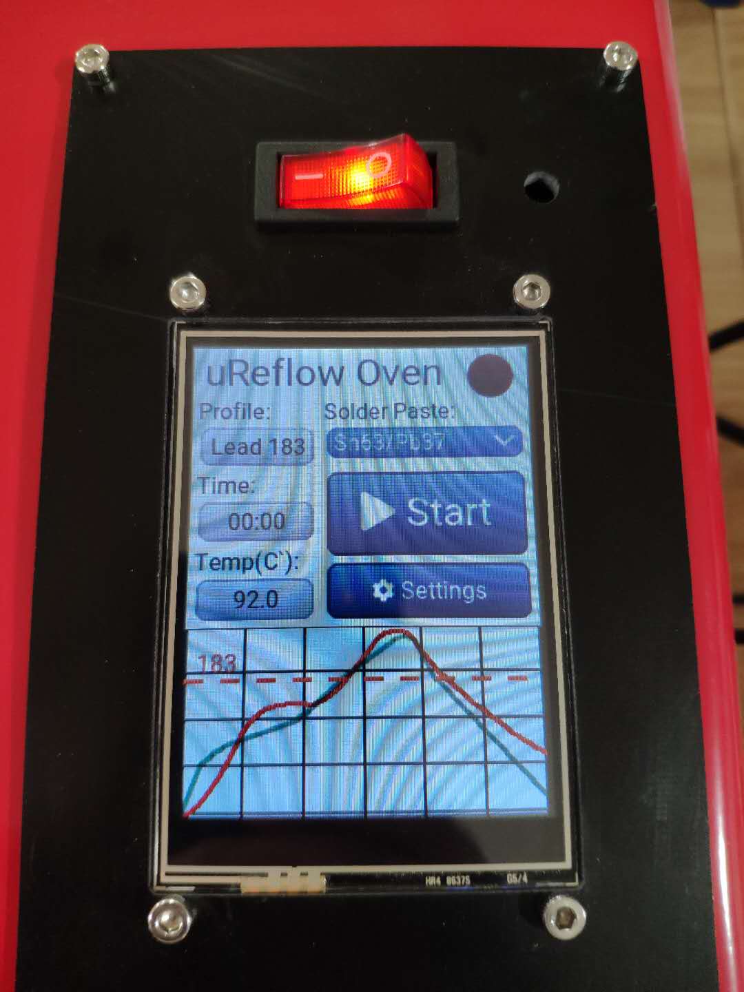
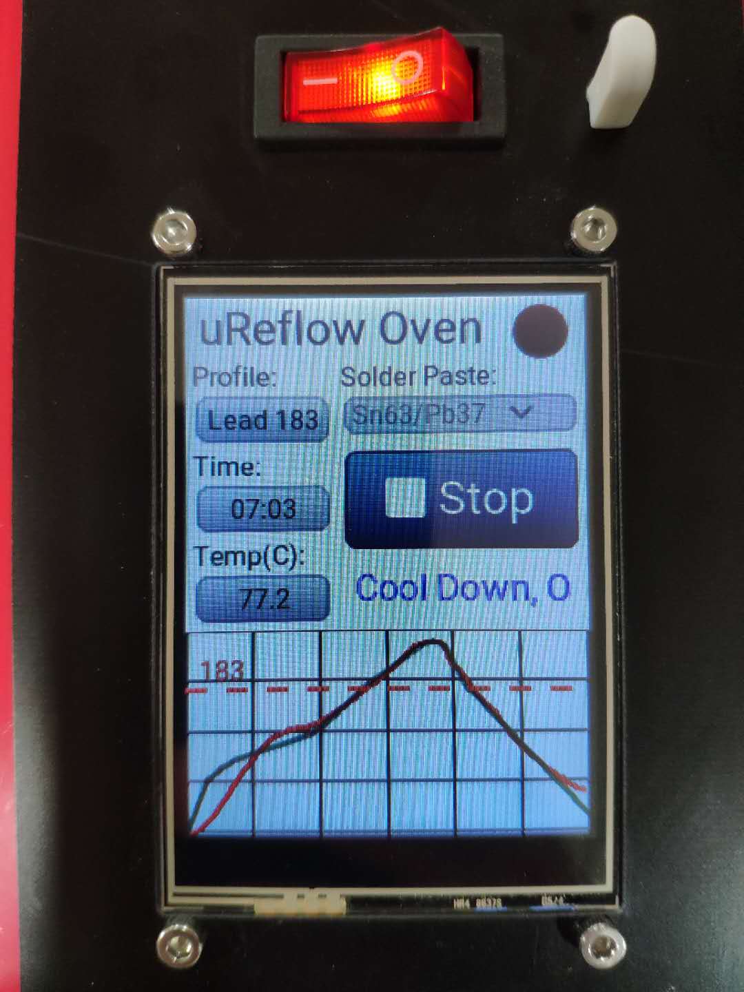
Update: The temperature control logic has been rewritten with PID.
There is a bit overshooting during the preheat stage, but after that, the temperature control is fairly good. (green line: ideal temp profile; red line: the actual temp)
I’m having software problems with your code: during calibration, temperatures are read without a problem, but during normal operation, I don’t get any temperatures.
On the serial terminal via USB, I’m seeing temperature values during calibration. The heater reaches its peak at about 125C which seems correct, then the board re-boots (I assume this is intended).
In normal mode, the temperature field in the display shows “—” and the serial console shows errors. It’s strange though, because during calibration it works fine. Any idea?
(This is still using the old code, I didn’t update to the PID version yet)
124.0
124.25
124.5
124.25
124.5
124.25
ets Jun  8 2016 00:22:57

rst:0xc (SW_CPU_RESET),boot:0x13 (SPI_FAST_FLASH_BOOT)
configsip: 0, SPIWP:0xee
clk_drv:0x00,q_drv:0x00,d_drv:0x00,cs0_drv:0x00,hd_drv:0x00,wp_drv:0x00
mode:DIO, clock div:2
load:0x3fff0018,len:4
load:0x3fff001c,len:4824
load:0x40078000,len:9652
load:0x40080400,len:6200
entry 0x400806f0
W (325) cpu_start: Chip revision is higher than the one configured in menuconfig. Suggest to upgrade it.
ILI9341 initialization completed
Enable backlight
Single buffer
Traceback (most recent call last):Error occurs when measuring temperature.

  File "main.py", line 149, in <module>
  File "oven_control.py", line 16, in __init__
Unhandled exception in thread started by p
                                           File "max31855.py", line 50, in read_temp
RuntimeError: thermocouple not connected<function measure_temp at 0x3fff98b0>
Traceback (most recent call last):
  File "main.py", line 132, in measure_temp
  File "max31855.py", line 68, in get_temp
  File "max31855.py", line 50, in read_temp
RuntimeError:
thermocouple not connected
MicroPython v1.9.4-2072-gf89c8c48c-dirty on 2020-01-17; ESP32 module with ESP32
Type "help()" for more information.I’m not quite sure what’s wrong by looking at the trace back as my old version of the main.py only has total 148 lines, but your error message said it was at line 149 of the main.py.
I took a look at your main.py in your github repo, it seemed that you created the instance of the GUI class after the thread which ran the measure_temp function in which it called the intance of the GUI class which was gui.
Would you try to change the order of the code?
Thank you for the support! The output pasted above came still from your old code (February 4th) with some quick fixes to adapt it to my hardware. Today I worked it into proper git commits and merged it with the newest version.
As you can see in my repo, I added a feature to configure the heater pin as low-active. I needed this because my solid state relay needs 5V to switch, so I’m working with a transistor that caused the logic to get inverted. I’m going to issue a pull request at some point, but I first need to test better. It worked with the old version - with the new version I cannot currently turn on the heater since the temperature measurements are failing.
What I localized so far is that the MAX31855 module reports “thermocouple not connected”. So I first assumed my thermocouple got destroyed, but with a different thermocouple I am getting the same error. I replicated what the code does manually in the REPL and I found that I’m always reading 0xFFFFFFFF from the sensor. This looks like either the chip is dead or the wiring is faulty. I verifed the CS pin with a multimeter - everything fine. I think I may have to dig out a logic analyzer to look at SCK and MISO.
Another possible cause is that the chip is not getting enough power, as I am taking the 3V3 from the ESP32 module. But the AMS1117 on that module supplies 1A, which should be plenty.
What is very strange though is that it worked before (see the output posted above) and literally after the reboot, it stopped working. I didn’t touch the hardware whatsoever, that’s why I thought it’s a software problem.
One thing that should be improved in the code is that there are multiple places where temperatures are read. The method main.measure_temp(), which seems to be a periodic GUI updater only, has a try-except-block. But oven_control calls get_temp in many different places as well, without exception handling. This should be changed and passed through one single function which does handle exceptions. That function should also turn off the heater if temperature reading fails or reports impossible values, as a safety measure to prevent overheating and fires.
Thanks for the advice.
For low-active device, I think the Signal class can be an elegant solution to this - I shall update my code later with Signal
Regarding the periodic timer calling the measure_temp() function, I intended to update the temp sensor reading by performing real time measurements with read_temp() and saved the result in the last_read property. For get_temp(), it simply get the value from last_read, this way I can always get the temp reading without waiting, although it may not be 100% real time, I think it’s ok in this use case. But I agree with you that I should have given more thoughts on safety measures.
for low-active heater:
oven = machine.Signal(machine.Pin(OVEN_PIN, machine.Pin.OUT), invert=True)
For the temp sensor error, I have no idea, have you tried running temp_cali.py again to see if it still works? Do you have a spare to test?
If you use multiple devices on one SPI line with different levels of CS signal then check it out:
I made a lot of improvements to the code:
Emergency off: whenever the temperature sensor reports a failure, shortcut or missing thermocouple, the heater is now automatically turned off immediately to prevent destruction of the PCB or fire.
Support for MAX6675 sensor (my MAX31855 is really dead, the dump above actually documents the moment it passed away I still had one MAX6675 lying around, so I wrote code to use that one instead. You can now configure in config.json which one you wish to use.
GUI now displays thermocouple errors (e.g. “NC” for “not connected”). This should be very useful for debugging while people build this project.
Fixed temperature caching (the concept was smart, but it didn’t work properly. oven_control never used cache values and always read new ones via SPI). Now you can also configure the max. temperature caching time seperately from the update interval of the temperature display.
WiFi SSID can now be configured in config.json
FTP can be turned on or off in config.json
Touch sensor is now only instantiated in one single place (instead of two if-branches).
More efficient parsing of the config file shrinks main.py by 40% to 109 lines
Application title can now be configured
I updated the English readme file. The Chinese one still needs updating. Could you please add me (pastaclub on github) as a collaborator so I can merge my improvements into the main repo?
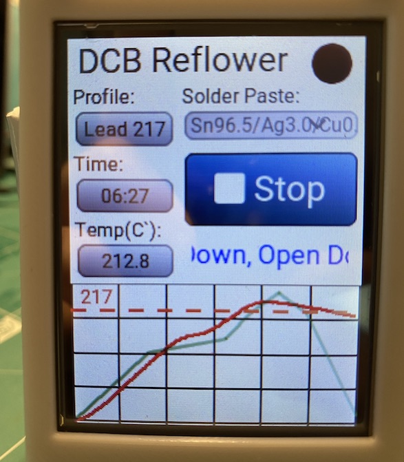
I guess I need to tune my machine now. Looking at my first test cycle with default PID values, the graph actually looks quite good already, but:
I’m fine tuning the heating behavior and temp control logic these days.
This was what I got after nearly 4 hours of testing and trying. The changes had been updated to ‘beta’ branch, if you care to take a look.
For PID tuning, set Kp value small enough and Kd big enough to prevent overshooting during the early stage, especially in the preheat and soak stage (I disabled Ki part until it reaches reflow stage in the most recent change, see beta branch), then slowly increase the value of Ki until the actual peak temp gets as close as the ideal peak temp. My own setting of PID is Kp=0.1, Ki=0.03, Kd=300.
BTW, I cooled the oven with a small USB fan which worked like a charm.
I will get in touch with you on github tomorrow - it’s already midnight here in China.
Your graph looks really good now! I hope I can get similar results. I guess PIDs will ultimately be hardware-dependent. My device is a hot-plate and it will behave different from an oven. I have already mounted fans to mine, but I’m not using them yet since I first need a 12V supply and a way to switch them. I also doubt they will help much. The plate takes 20 minutes or so to go back under 40C. That way it’s no fun to try different PIDs.
Yes, let’s merge the repos, otherwise it will get more and more difficult to merge the changes later. My changes should not break anything on your side (at least not something that’s not fixed by editing config.json)
I just added you on github and left a message for you in issues.