My LCD does not display whole screen

Important: unclear posts may not receive useful answers.

Before posting

  • Get familiar with Markdown to format and structure your post
  • Be sure to update lvgl from the latest version from the master branch.
  • Be sure you have checked the FAQ and read the relevant part of the documentation.
  • If applicable use the Simulator to eliminate hardware related issues.

Delete this section if you read and applied the mentioned points.

Description

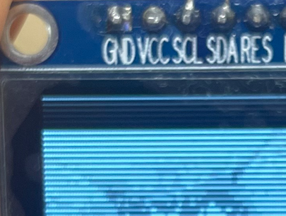
What MCU/Processor/Board and compiler are you using?

STM32L476RG

What LVGL version are you using?

v8.3

What do you want to achieve?

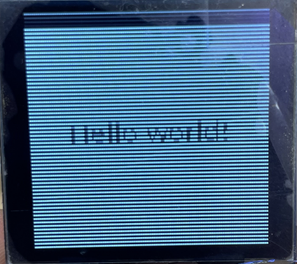
I want to print it out on the entire LCD screen, but the garbage value is printed on top.

What have you tried so far?

Code to reproduce

Add a code snippet which can run in the simulator. It should contain only the relevant code that compiles without errors when separated from your main code base.

The code block(s) should be formatted like:

/*You code here*/

This is my lvgl init code.

void Display_init(void)
{
lv_init();

static lv_disp_draw_buf_t disp_buf;
static lv_color_t buf_1[DISP_BUF_SIZE];

lv_disp_draw_buf_init(&disp_buf, buf_1, NULL, DISP_BUF_SIZE);

// Driver
lv_disp_drv_init(&disp_drv);

disp_drv.draw_buf = &disp_buf;
disp_drv.flush_cb = my_flush_cb;
disp_drv.hor_res = SSD1327_LCDWIDTH;
disp_drv.ver_res = SSD1327_LCDHEIGHT;
disp_drv.sw_rotate = 1;

lv_theme_mono_init(0, false, NULL);
lv_theme_mono_is_inited();

disp = lv_disp_drv_register(&disp_drv);
lv_disp_set_rotation(disp, LV_DISP_ROT_NONE);

LV_IMG_DECLARE(test_image2);

// LV_IMG_DECLARE(img_lvgl_logo);
img1 = lv_img_create(lv_scr_act());
lv_img_set_src(img1, &test_image2);
lv_obj_align(img1, LV_ALIGN_CENTER, 0, 0);
lv_obj_set_size(img1, 128, 128);

lv_obj_t * img2 = lv_img_create(lv_scr_act());
lv_img_set_src(img2, LV_SYMBOL_OK "Accept");
lv_obj_align_to(img2, img1, LV_ALIGN_OUT_BOTTOM_MID, 0, 20);

}

And This is my flush callback function.

static void my_flush_cb(lv_disp_drv_t *disp_drv, const lv_area_t *area, lv_color_t *color_p)
{
if(area->x2 < 0 || area->y2 < 0)
return;
if(area->x1 > SSD1327_LCDWIDTH -1) return;
if(area->y1 > SSD1327_LCDHEIGHT -1) return;

int16_t x, y;
uint8_t *buf = (uint8_t*) color_p;

for(y = area->y1; y <= area->y2; y++) {
	lcd_setwindow();
	for(x = area->x1; x <= area->x2; x++) {
		SSD1327_DrawPixel(x, y, (uint8_t)color_p->full);
		color_p++;
	}
}

lv_disp_flush_ready(disp_drv);

}

And I don’t know how to display whole screen.

Screenshot and/or video

If possible, add screenshots and/or videos about the current state.
d

Did you properly setup the x and y resolutions, the color depth?
You also set lvgl for doing software rotation disp_drv.sw_rotate = 1;.
Is this intended?

My lcd is 128*128. So I set the height to 128 and the width to 128. And I set sw_rotation to 1 to rotate the image. However, the image does not rotate. Do you happen to know how?

Sorry this is a bit little information you provide.
Your screenshot shows only a little part of the full image.
You did not provide the color depth.
You did not provide the display type (we just see from the code it’s something like SSD1327).
What controller board do you use?
Did you try to setup lvlg without software rotation.
What do you want to rotate? The image you want to show, or the whole screen.
What SSD1327 library do you use?
Did you try to show only a simple lvgl widget without any image?
The little screenshot of the display shows horizontal stripes (dark and bright). That looks strange.

Color depth used 8. The LCD is using SSD1327. The board is using STM32L476RG. I tried to set it up without rotation, but the upper line is not displayed. I want to rotate the image when I press the external hardware button. I am using the SSD1327 library that I made myself. The SSD1327 Draw Pixel function is striped to see if it is written strangely. I don’t know which SSD1327 driver to use. Here’s my SSD1327 DrawPixel function.

void SSD1327_DrawPixel(int16_t x, int16_t y, uint8_t Color)
{
	 if ((x < 0) || (x >= SSD1327_LCDWIDTH) || (y < 0) || (y >= SSD1327_LCDHEIGHT))
		 return;

	 uint8_t SelectedCell = buffer[x/2 + y*(SSD1327_LCDWIDTH/2)];

	 if(x % 2)
	 {
//		 SelectedCell = (SelectedCell & 0x0f) | (Color<<4);
		 SelectedCell &= ~(0x0F);
		 SelectedCell |= (0x0F & Color);
	 }
	 else
	 {
//		 SelectedCell = (SelectedCell & 0xf0) | (Color);
		 SelectedCell &= ~(0xF0);
		 SelectedCell |= (0xF0 & (Color<<4));
	 }

	 buffer[x/2 + y*(SSD1327_LCDWIDTH/2)] = SelectedCell;
}

Should the use of frame buffers and the code used by the driver and the buffer used by the SSD1327 be in the same C code?

This is my LCD display.
캡처

STM32L476RG is the name of the microcontroller but not the name of the board where this microcontroller is attached to .
SSD1327 is the name of the display controller but not the name of the display module where this display controller is attached to.
How is the display connected to the microcontroller (via SPI, I2C?) I don’t see any code writing to the display.

In your SSD1327_DrawPixel function you read from the array buffer and you write to the array buffer. That is strange.
I don’t see any declaration for the array buffer

How is lvgl setup (color depth in lv_conf.h)? Also for 8-bit?
Your screenshot indeed shows the Hello world! (which is good), but only every second horizontal display line is shown.

The buffer which lvgl uses for drawing into is/should not the same as the display’s frame buffer.
lvgl draws into a working buffer (your buf_1) and you are responsible for transferring the data into the frame buffer which the display uses it. Depending on the used display this can be a build in framebuffer on the display module, or
a frame buffer which is build into the microcontroller if you use directly connected (‘dump’) displays and the micro controllers build in LCD controller (available on some STM32 controllers and also other controller families).

The buffer declaration was declared in the ssd1327 driver header file.

// Buffer
#define SSD1327_BUFFERSIZE	(SSD1327_LCDHEIGHT * SSD1327_LCDWIDTH / 2)
static uint8_t buffer[SSD1327_BUFFERSIZE];

And my SSD1327_DrawPixel function.

void SSD1327_DrawPixel(int16_t x, int16_t y, uint8_t Color)
{
	 if ((x < 0) || (x >= SSD1327_LCDWIDTH) || (y < 0) || (y >= SSD1327_LCDHEIGHT))
		 return;

	 uint8_t SelectedCell = buffer[x/2 + y*(SSD1327_LCDWIDTH/2)];

	 if(x % 2)
	 {
		 SelectedCell &= ~(0x0F);
		 SelectedCell |= (0x0F & Color);
	 }
	 else
	 {
		 SelectedCell &= ~(0xF0);
		 SelectedCell |= (0xF0 & (Color<<4));
	 }

	 buffer[x/2 + y*(SSD1327_LCDWIDTH/2)] = SelectedCell;
}

SSD1327, and the LCD I use is zjy-mi50.
I didn’t know the color depth of this, so I tried various depth, and as a result, 8 color depth is the best output, so I’m using it. I don’t know why only the second horizontal line is printed.

The disp_buf that lvgl uses for drawing uses a size of [hor_res * 10].
( hor_res = 128)

When you first draw in the init part, the image is not printed on the full screen, but from the second drawing, it is printed on the full screen. Do you know why?

I did not find anything with zjy-mi50 but with zjy-mi150.
It’s an OLED display 128x128 from EC Buying. I find the following datasheet.
The color depth is 4-bit (16 grayscale colors).

Your flush call back function (my_flush_cb) write the lvgl working buffer to the intermediate array buffer, but not directly to the display.
Where is the function where you write the buffer to the display, and when is it called?
Usually the display data is transferred from lvgl’s working buffer to the display within the flush call back function.
In this case only the relevant data has to be transmitted to the display.

You set up lvgl for 8-bit (RGB332) color depth. Within the function SSD1327_DrawPixel you only write the lower 4-bits of the 8-bit color. How to you make sure that you only use the colors from 0x00 to 0x0f within lvgl?

Show your code where buffer[] is sending to display.
DMA FMC SPI ??? lcd_setwindow();???
Code what you showed is waste of power , but seems ok handle image to mem only.

I saw it wrong. The zjy-m150 model is correct.
The ability to write buffers to the display was created at the end of the flush_cb function. I’m not sure if I can fill it out like this. However, I am using it like this because it is displayed on the screen. Is this the right way to change the buffer contents with the flush_cb function and then order the buffer contents to be sent to the LCD through I2C communication?

static void my_flush_cb(lv_disp_drv_t *disp_drv, const lv_area_t *area, lv_color_t *color_p)
{
	int16_t x, y;
	uint8_t *buf = (uint8_t*) color_p;

	for(y = area->y1; y <= area->y2; y++) {

		for(x = area->x1; x <= area->x2; x++) {
			SSD1327_DrawPixel(x, y, (uint8_t)color_p->full);
			color_p++;
		}
	}

	lv_disp_flush_ready(disp_drv);
	SSD1327_Display();

}

void SSD1327_Display(void)
{
	SSD1327_Command(SSD1327_SETCOLUMNADDRESS);
	SSD1327_Command(0x00);
	SSD1327_Command(0x3F);

	SSD1327_Command(SSD1327_SETROWADDRESS);
	SSD1327_Command(0x00);
	SSD1327_Command(0x7F);

#ifdef SSD1327_I2C_CONTROL
#ifdef SSD1327_I2C_DMA_ENABLE

	if(ssd1337_i2c->hdmatx->State == HAL_DMA_STATE_READY)
	{
		HAL_I2C_Mem_Write_DMA(ssd1337_i2c, SSD1327_I2C_ADDRESS, 0x40, 1, (uint8_t*)&buffer, SSD1327_BUFFERSIZE);

	}
#else
	HAL_I2C_Mem_Write(ssd1337_i2c, SSD1327_I2C_ADDRESS, 0x40, 1, (uint8_t*)&buffer, SSD1327_BUFFERSIZE, 1000);
#endif
}


I noticed that lvgl uses 8 bits but the LCD I use only 4 bits. Because of this, the image is not being displayed in the correct color. I don’t know how to write only the bottom 4 bits in lvgl. Do you know how?

I am writing the contents to the buffer as a function of flush_cb and sending the contents of the buffer to I2C. I don’t know if this is the right way to write it.

static void my_flush_cb(lv_disp_drv_t *disp_drv, const lv_area_t *area, lv_color_t *color_p)
{
	int16_t x, y;
	uint8_t *buf = (uint8_t*) color_p;

	for(y = area->y1; y <= area->y2; y++) {

		for(x = area->x1; x <= area->x2; x++) {
			SSD1327_DrawPixel(x, y, (uint8_t)color_p->full);
			color_p++;
		}
	}

	lv_disp_flush_ready(disp_drv);
	SSD1327_Display();

}

void SSD1327_DrawPixel(int16_t x, int16_t y, uint8_t Color)
{
	 if ((x < 0) || (x >= SSD1327_LCDWIDTH) || (y < 0) || (y >= SSD1327_LCDHEIGHT))
		 return;

	 uint8_t SelectedCell = buffer[x/2 + y*(SSD1327_LCDWIDTH/2)];

	 if(x % 2)
	 {
		 SelectedCell &= ~(0x0F);
		 SelectedCell |= (0x0F & Color);
	 }
	 else
	 {
		 SelectedCell &= ~(0xF0);
		 SelectedCell |= (0xF0 & (Color<<4));
	 }

	 buffer[x/2 + y*(SSD1327_LCDWIDTH/2)] = SelectedCell;
}

void SSD1327_Display(void)
{
	SSD1327_Command(SSD1327_SETCOLUMNADDRESS);
	SSD1327_Command(0x00);
	SSD1327_Command(0x3F);

	SSD1327_Command(SSD1327_SETROWADDRESS);
	SSD1327_Command(0x00);
	SSD1327_Command(0x7F);

#ifdef SSD1327_I2C_CONTROL
#ifdef SSD1327_I2C_DMA_ENABLE

	if(ssd1337_i2c->hdmatx->State == HAL_DMA_STATE_READY)
	{
		HAL_I2C_Mem_Write_DMA(ssd1337_i2c, SSD1327_I2C_ADDRESS, 0x40, 1, (uint8_t*)&buffer, SSD1327_BUFFERSIZE);

	}
#else
	HAL_I2C_Mem_Write(ssd1337_i2c, SSD1327_I2C_ADDRESS, 0x40, 1, (uint8_t*)&buffer, SSD1327_BUFFERSIZE, 1000);
#endif
}


I’m using I2C and DMA now.
The lcd_setwindow() function is used as a function to specify the drawing position on the LCD.
But I’m not using it now.

void lcd_setwindow(void)
{
	SSD1327_Command(SSD1327_SETCOLUMNADDRESS);
	SSD1327_Command(0x00);
	SSD1327_Command(0x3F);

	SSD1327_Command(SSD1327_SETROWADDRESS);
	SSD1327_Command(0x00);
	SSD1327_Command(0x7F);
}

What do you mean it’s a waste of power but it’s okay to use it only for mems? I don’t quite understand. Can you explain?

You try allways send full screen = first misstake
DMA dont block code then your flush can repeat when data isnt completely send 2 mistake
full screen buffer in memory = 3 waste space mistake

my_flush_cb(lv_disp_drv_t *disp_drv, const lv_area_t *area
is directly designed to send to display , then write it.
And sended is not full screen, but area only.

Then should I tell them to send only the modified part without sending the entire screen? How do I modify it?

For example first test, but more effective is implement all in flush…

Let’s go back to find out the primary problem.

  1. The code you showed within your first post does not match with the screenshot you post later.
    Your code is something with images, but your screenshot shows the Hello world!

  2. The screenshot (the second, overall view) shows two abnormalities:

  • The main one, we see alternating horizontal lines (a dark one and a bright one which seems to show the correct image).
  • On top of the screen we see some darker rectangle. As long as we do not have the correct source code we can not say what it is (where it does come from!). For that we would need the correct source code.

Maybe you can do the following:
On top of your SSD1327_Display function do a test fill of your buffer with a specific pattern.
E.g.

for (uint16_t y = 0; y < 128; y++) {
    for (uint16_t x = 0; x < 64; x++) {
        buffer[x + (y * 64)] = (y / 8) | (y / 8) << 4;
    }
}

Now you should see 16 fields of different gray. Top should be black, and white at the bottom.
If you see again the alternating horizontal lines than the problem is related to the display controller.

And little match if I2C is 100kHz then one frame took around 750ms aka your refresh rate is around 1 frame per second.

I’m already implementing it this way…

No you start sending address before check DMA is complete.
If you plan use DMA your code must be more complicated. For example DMA ready isnt marker that all I2C data is sended from FIFOs usw.

I try explain your code:

  1. first cbflush update in buffer only part of display , because lvgl update in blocks. And after this start SSD1327_Display() full screen refresh
  2. here is started DMA and load display all took 750ms on 100kHz
  3. DMA is on background and your code continue cbflush next part update in buff and repeat call SSD1327_Display , but here previous DMA is executed…
    But you force send SSD1327_Command(SSD1327_SETCOLUMNADDRESS);
    SSD1327_Command(0x00);
    SSD1327_Command(0x3F);…
  4. Result is corrupt communication maybe, based on Command code… you dont show i mean black lines is this.