Starting a new thread, because my memory-related issue is solved and the actual problem is totally unrelated. I’m stuck with a white screen because there is no activity on the CLK line.
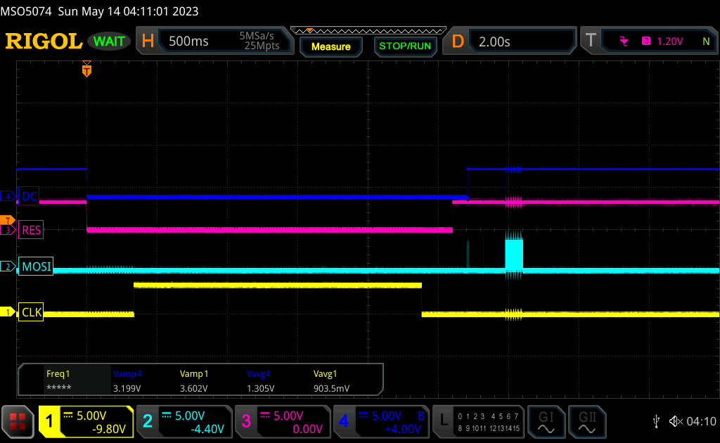
Other than a long pulse at init, there are no edges on the CLK line. You can see a burst of data being shifted out on MOSI around 3s after the RST line is asserted, but no corresponding CLK pulses. I have looked around at other times later in the capture, and I can see activity on DC and lots of data on MOSI, but never any clock pulses.
I have main.py in the ESP’s flash, with the following contents:
import lvgl as lv
from ili9XXX import ili9341
import espidf as esp
import time
from machine import Pin

disp = ili9341(factor=16, mhz=10, miso=12, mosi=13, clk=14, cs=4,
               dc=27, rst=26, spihost=esp.HSPI_HOST)

scr = lv.obj()
btn = lv.btn(scr)
btn.align_to(lv.scr_act(), lv.ALIGN.CENTER, 0, 0)
label = lv.label(btn)
label.set_text("Hello World!")
lv.scr_load(scr)
I have also tried the following code to wiggle the pin directly and it works as expected:
from machine import Pin

clk = Pin(14, Pin.OUT)

while True:
    clk.on()
    time.sleep_ms(200)
    clk.off()
    time.sleep_ms(200)
Anyone got any idea what may be causing this?
Finally, a related supplemental question - how do I initialise the display object without providing a CS line? My display doesn’t have one, and setting cs=None produces an error.
Using VSPI_HOST fixed it but, interestingly, simply replacing HSPI_HOST with VSPI_HOST wasn’t enough. That produced identical behaviour with activity on MOSI but not CLK. This is weird, because on the ESP32 any signal can be routed to any pin via the GPIO matrix. (Yes, it’s advantageous to use the dedicated mappings for the two SPI buses because they can be driven slightly faster without the GPIO matrix in the signal path).
What worked was switching to VSPI with its dedicated pins (clk=18, mosi=23). I now have Hello World working.
So that leaves two open questions:
Why doesn’t the HSPI CLK line work (on its dedicated pin)?
Why does the VSPI CLK line work only on its dedicated pin, and not through the GPIO matrix (even at the low speed of 10MHz)?
Seems like this important info should be in the docs somewhere. Shall I submit a PR to lv_binding_micropython/blob/master/README.md?
I also guessed, from that README, that you can set cs=-1 the same way you can set miso=-1. It works.
Well, on my side I use HSPI_HOST with miso=5, mosi=18, clk=19 which means they are routed through the GPIO matrix. According to the docs that should work fine up to 40Mhz and it really does.
I don’t know why only VSPI worked for you, and why GPIO matrix didn’t, but according to the specs and according to my experience this is not a true limitation as you suggest.
I think there might be something else we are missing that causes the problem you experienced.
Well that’s extremely weird. Since there are no hardware differences I guess this must be something to do with a slightly different build - version of IDF/mpy or some other subtle difference.
This precise model ( Rigol MSO5074 ) is quite capable. While it has a bandwidth of 70MHz, the sampling rate is 8Gsps divided by the number of channels in use: 8Gsps for one channel, 4Gsps for two, and 2Gsps when using all four channels.
So it should be more than enough to display the clock signal. That said, reducing the SPI bus clock speed makes it easier to troubleshoot.
And sure, a wise use of trigger is useful to catch the precise moment the communication occurs on the SPI bus
Yeah I’m sure it’s not a measurement issue - I’ve looked at multiple timescales and it’s totally dead - just no edge transitions at all after the long pulse on init.
It can’t be the MCU, because flaws almost never occur in silicon that’s left the fab. More likely would be an assembly flaw in the cheap module PCB, like a dodgy solder joint or shorted trace, but that’s not the cause because I have shown that the MCU can wiggle the pin fine. Also possible (but very rare) would be static damage but the pin wiggling disproves that too.
It has to be software, but I have no idea how to go about debugging it.
I’m following the “Alternative Example” under “Super Simple Example” in the docs for lv_micropython. There is just the instantiation of the ili9341 object, no callbacks/init.
all of the flush callbacks are handled in the class that you are initilizing.
-1 for the CS is what you set when it is not used. Keep in mind that since the CS line for your display is pulled low and not connected to the MCU you are not going to be able to have more than that single display on the bus. This is due to the display always “listening” so any data that would get sent to a different device would be picked up by the display and you would end up with some funky problems because of it.
There are low cost displays out there that are real junk and there are others that are pretty decent. It’s a crap shoot. You should be able to get the SPI speed up to 80MHz if the display and board is of a good quality.
When you have the display connected and everything powered up but you do not have the driver set up or the SPI running what is the state of the clock pin? It should be pulled either high or low. I cannot remember which. It could be the pin is pulled in the wrong direction or it’s not being pulled at all. I would check on that and read up to see what the clock line is supposed to be pulled to.
Yes, I inferred from the docs that I could use -1 for CS, as the CS line isn’t broken out on my display. It isn’t stated explicitly in the docs - rather it is mentioned in the context of miso - but it works anyway. I have also tried assigning a pin regardless. In either case, the behaviour is identical.
The thing is, regardless of clock speed or initial state, there is simply no activity on the clock signal at all, other than a long pulse on init. This means the SPI peripheral must not be configured correctly. Perhaps it is not enabled, or an internal clock line isn’t gated into it, or its clock is not running, or is not in the right frequency range, or an interrupt flag bit needs clearing, etc. All the kind of nonsense you’d ideally like to not have to think about when using micropython .
I think the way forward is to attach a JTAG debug probe and read the SPI configuration registers. I haven’t tried JTAG on an ESP32, so I’m hesitant to learn the nitty gritty, particularly since I can just use the VSPI bus. Perhaps I can make time to try.
Here is the thing tho. the clock line is only going to get pulsed in one direction either high or low. I believe it is going to be high. That means it is the responsibility of the display to pull it down. If instead there is something not set up right on the display and it’s being pulled up then you are not going to see a state change on the pin at all except when maybe the display gets reset you might see a hiccup on that line.
the other question is this. Is there supposed to be clock pulses in the traditional sense? I do not know what the SPI standard says but it could be that the clock line is supposed to only have that single burst which tells the devices on the bus what the speed is.
I would have to look at the specification. It seems that would be a complete waste of a pin but that might be how it’s supposed to work… dunno…
SPI is a “synchronous” serial bus. Each bit on the data line is clocked into the slave on an edge on the clock line. So every data bit is synchronised to exactly one clock pulse, hence the name. This is a simple way of communicating at >>10x the speed an asynchronous serial bus (e.g. RS232) can reach. As you mention, tens of MHz are no problem at all, even on janky modules on breadboard with long, flailing jumper wires.
So no, certainly not a waste - a good old clock pin working in the most traditional way imaginable.
No. In SPI, the clock and data lines are driven entirely by the bus master (the ESP32 in this case). I have never encountered any situation in electronics in which different edges of the same signal are driven by different hosts, but I’m sure there’s an exception somewhere.
yeah I went and read up on SPI. so the clock line should be pulsing like a bandit. and it is working in VSPI. that leads me to think it is a hardware issue. The same mechanics used to set up SPI are used with HSPI and VSPI alike. so if it was a software issue in LVGL then it wouldn’t be working all together. LVGL doesn’t use the SPI handling that is built into MicroPython. is uses the ESPIDF directly so that removes MicroPython from the equation. The problem either lies in the ESPIDF (which I would imagine this problem would have been reported) or it is a hardware related issue.