if using DC voltage what is the current draw? Might be easier to locate a motor driver that is I2C where you would actually be able to use PWM to control how open the solenoid is if you were interested in having a variable position on those solenoid valves. That’s if it is DC power, just need to know the amperage each solenoid would draw to size things properly.
I need to open/close some solenoid valves, like these one (DC 12v) 6.94€ 24% di SCONTO|Elettrovalvola elettrica in plastica 12V 24V 220V normale chiusa 1/4
I’m now writing about my actual setup, with the Arduino 2. I’m waiting for the new ESP32 and expansion board (that maybe is not needed) to start again the development ![]()
I have this 7” 800x480 Display, it already has an ESP32-S3. It uses the Arduino_GFX library and is fast. I also have another 7” display with SSD1963 and a separate ESP32-S3 using the mcufriend library and the same widgets example, but it is very slow, so this needs improvement.
The problem is there are not a whole lot of pins left for external uses.
Ciao!
Just arrived the new hardware!The new ESP32 S3, i’ve checked and i’ve all the pins already on board.
The display is an ILI9488 3.9" with touch chip XPT2046.
Until now,i’ve some issue on how connect the display to the ESP32 board, can someone help me with this stuff?
I can’t have the touch working, in TFT_espi i can’t either find the calibration .ino file to calibrate the display.
Thanks in advance! ![]()
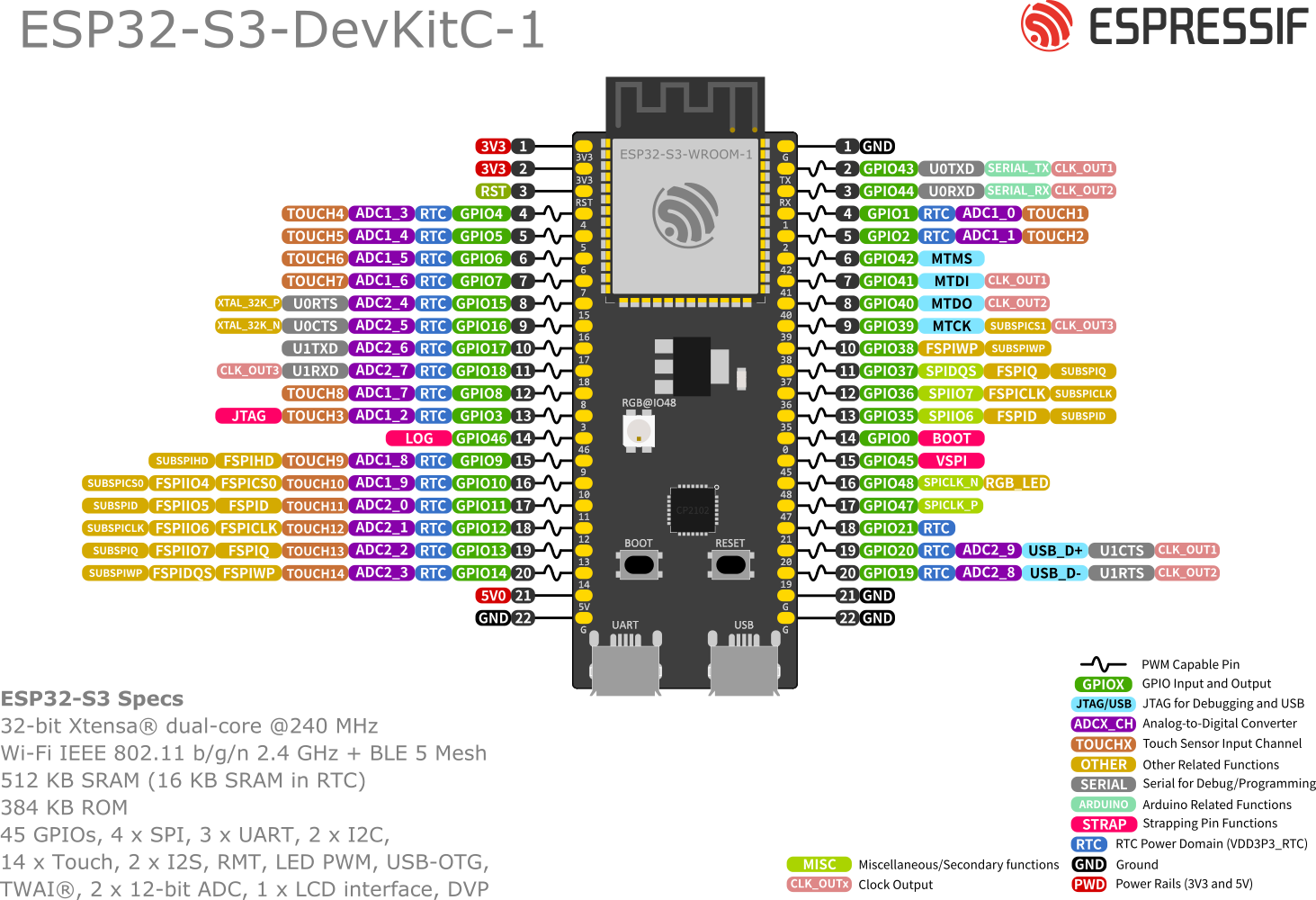
Just to be clear this is the pinout of the ESP32 S3 i’ve bought
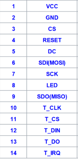
And this si the display i’ve bought Scheda base connettore adattatore display LCD TFT SPI da 4.0 pollici MCU I8080 8/16BIT 3/4 fili porta seriale parallela ILI9488 320x480|Moduli LCD| - AliExpress
With the pin-out
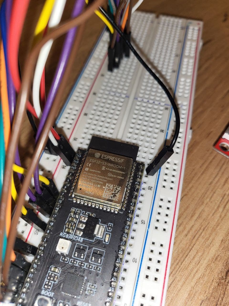
Actually my pins are connected in this way :
ESP32 → DISPLAY
3.3 → VDO
G → GND
4 → CS
5 → RST
6 → D/C
11 → SDI & TDI
12 → SCK & TCK
3.3 → BL
15 → TCS
16 → TDO
14 → PEN
need to know some more information.
did you get the devkit 1.0 or the 1.1?
the full model number of the devkit will look something like this.
ESP32-S3-WROOM-2-N16R8V
or possibly this
ESP32-S3-2-N16R8V
what I need to know is that last section the N16R8V which can look like this as well. N8
That series of numbers tells me how much flash and memory the board has but more importantly is also tells me which pins are available for use. if you have the board with 8mb of ram (R8) there are 4 pins that are not going to be available for you to use vs say a board with 2mb of ram (R2). The board that has 2mb of ram also has slower ram than the board that has 8MB. This make a large difference in performance due to the large display buffers that have data transferred in and out of the memory.
Hopefully you got a board that has R8 in that last section. The memory will be 2 times faster than the one that has R2 and if you do not have any R number in the last section it’s not the end of the world but it will limit what you are going to be able to do because you are going to have to keep your entire program within the constraints of the 512KB of SRAM (which is the fastest memory on the ESP32-S3). Ideally you want to get your display buffers into that 512KB of SRAM and if you have the SPIRAM available then you can use a little bit larger flush buffers and the rest of the program can overflow into that slower memory.
So get me that last section of the model number as we can go from there.
Ciao!Thanks for your answer.
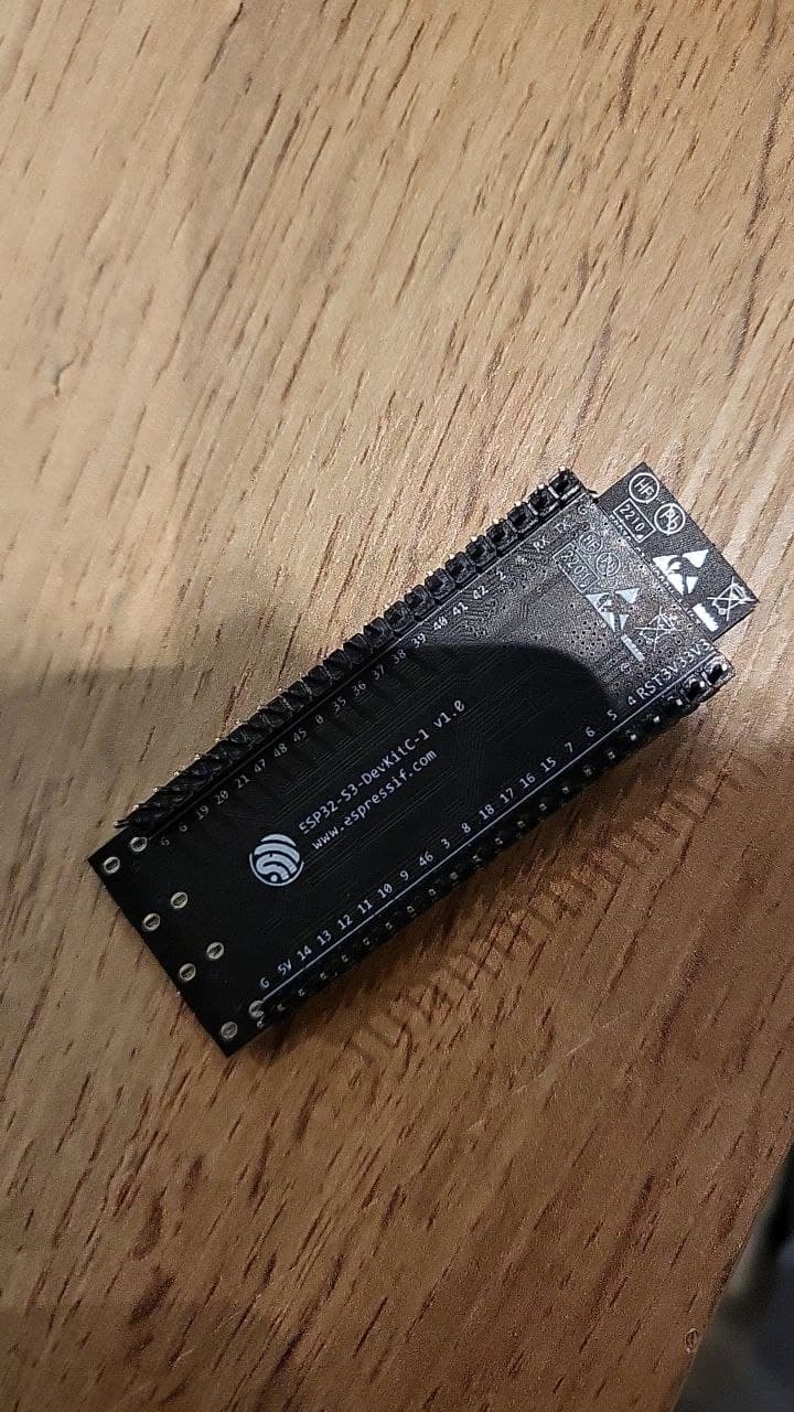
What i’ve actually is this one : ESP32-S3-DevKitC-1 8MB Flash 2MB PSRAN N8(8MB Flash)
If there us a better way to know what is the correct release of the board, just tell me!
Thanks for you help! ![]()
Here below a picture of the board! I believe is 1.0 Board
Ciao @kdschlosser ,
finally i’ve found how to connect the board with the display, here is the list of pins :
ESP32 S3 → DISPLAY
- 3.3→ VDO
- G → GND
- 10 → CS
- 6 → RST
- 7 → D/C
- 11 → SDI (MOSI) & TDI
- 12 → SCK & TCK
- 3.3 → BL
- Not Used → SDO (MISO)
- 16 → TCS
- 13 → TDO
- Not Used → PEN
I’ve used the Setup21_ILI9488.h config file from TFT_eSPI library , and defined in this way :
// See SetupX_Template.h for all options available
#define USER_SETUP_ID 21

#define ILI9488_DRIVER

//#define TFT_INVERSION_OFF

//WORKING ON ESP32
//#define TFT_MISO 19 // (leave TFT SDO disconnected if other SPI devices share MISO)
//#define TFT_MOSI 23
//#define TFT_SCLK 18
//#define TFT_CS   15  // Chip select control pin
//#define TFT_DC   2  // Data Command control pin
//#define TFT_RST  4  // Reset pin (could connect to RST pin)
//#define TOUCH_CS 22

//WORKING ON ESP32S3
#define TFT_CS   10 //     10 or 34 (FSPI CS0)
#define TFT_MOSI 11 //     11 or 35 (FSPI D)
#define TFT_SCLK 12 //     12 or 36 (FSPI CLK)
#define TFT_MISO 13 //     13 or 37 (FSPI Q)
#define TFT_DC    7
#define TFT_RST   6
#define TOUCH_CS 16 // Optional for touch screen

#define LOAD_GLCD   // Font 1. Original Adafruit 8 pixel font needs ~1820 bytes in FLASH
#define LOAD_FONT2  // Font 2. Small 16 pixel high font, needs ~3534 bytes in FLASH, 96 characters
#define LOAD_FONT4  // Font 4. Medium 26 pixel high font, needs ~5848 bytes in FLASH, 96 characters
#define LOAD_FONT6  // Font 6. Large 48 pixel font, needs ~2666 bytes in FLASH, only characters 1234567890:-.apm
#define LOAD_FONT7  // Font 7. 7 segment 48 pixel font, needs ~2438 bytes in FLASH, only characters 1234567890:.
#define LOAD_FONT8  // Font 8. Large 75 pixel font needs ~3256 bytes in FLASH, only characters 1234567890:-.
#define LOAD_GFXFF  // FreeFonts. Include access to the 48 Adafruit_GFX free fonts FF1 to FF48 and custom fonts

#define SMOOTH_FONT


// #define SPI_FREQUENCY  20000000
#define SPI_FREQUENCY  27000000
// #define SPI_FREQUENCY  40000000
// #define SPI_FREQUENCY  80000000

// Optional reduced SPI frequency for reading TFT
#define SPI_READ_FREQUENCY  16000000

#define SPI_TOUCH_FREQUENCY  2500000
I’ve enabled the
#define ILI9488_DRIVER
in the file User_Setup.h
and enabled
#include <User_Setups/Setup21_ILI9488.h>
in the file User_Setup_Select.h
Actually i’ve tested the On_Off_Button.ino, and the calibration was done without issue.
However i belive that my screen is not good…the display is always flickering if i barely touch it…
I’m trying now to have the SD card working…
I’ve found an example where the pins used are the following for ESP32 devkit board :
5→ CS
18 → CLK
19 → MISO
23 → MOSI
how can i wire on ESP32 S3 instead?
I’ve changed the in :
1→ CS (I don’t know if there is a specific pin for this, so i can’t use the first spare one on board…)
12 → CLK
13 → MISO
11 → MOSI
I’m running a code to load some jpg file from the SD card, i see on serial output this stuff :
open(): mountain.jpg does not start with /
All the images are in the root of the SD card.
The code is from here : ILI9341 TFT LCD to ESP32 - Full HOW TO - XTronical
Actually i see strange white lines coming from top to bottom of the screen
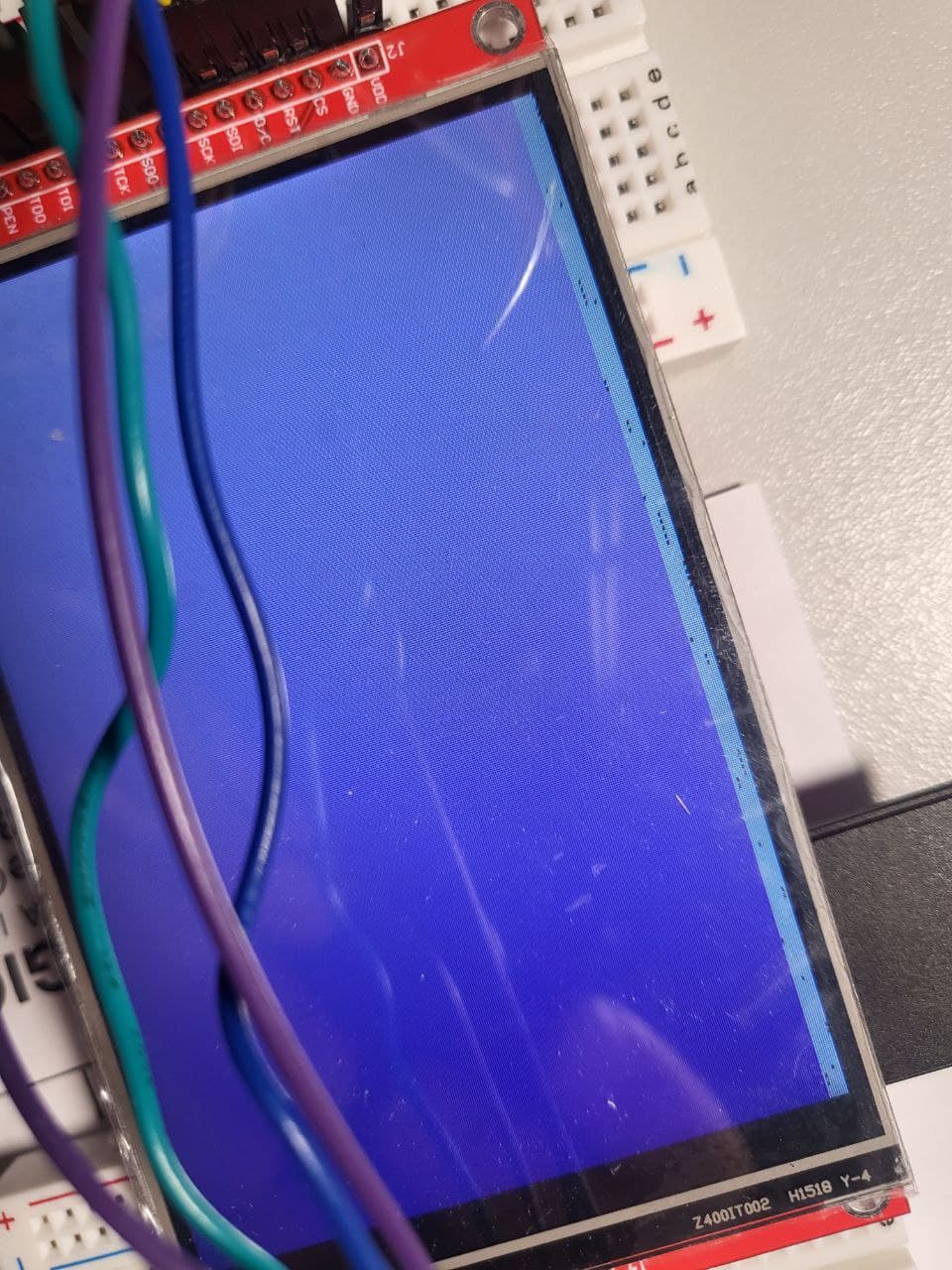
Do you have any hint!? ![]()
Stay away from the SDcard stuff for right now as it adds another layer of complexity. create a simple label and center it in the screen. see if that works without any problems. Some of these display boards can be fickle with the SDCard readers and to be honest you really do not need it unless there is a want to load images in a dynamic fashion. If the images are to be used as UI Elements you can use the LVGL image converter and convert them to C header files.
Once you get just a basic label displayed up the SPI speed.
#define SPI_FREQUENCY 27000000
change that to 40000000 and if that works change it to 80000000 and see if that works,
Actually i don’t need complex stuff to do, i just need to save something to be loaded ad start-up, like preferences, or save some icons for the UI…but i can convert into c-array in this case as you suggested!
What SPI_FREQUENCY is for?!
It’s the speed the data can be sent to the display. it’s basically bits per second. so the higher the number the faster the data is able to be sent. Displays that are made decent will be able to support 80mHz (80,000,000bps) so long as the IC supports it. I believe the display IC you are using supports 80mHz or at least 40.
Just tested, works only with 27000000, 40000000 and 80000000 results in a complete white screen ![]()
I’m doing wrong something?Maybe i need to setup other stuff also!?
Coming back to SD topic, i’ve figured out what are the correct pins :
10→ CS
12 → CLK
13 → MISO
11 → MOSI
I’ve found a sketch that simply print the correct values :
//Find the default SPI pins for your board
//Make sure you have the right board selected in Tools > Boards
void setup() {
  // put your setup code here, to run once:
  Serial.begin(115200);
  Serial.print("MOSI: ");
  Serial.println(MOSI);
  Serial.print("MISO: ");
  Serial.println(MISO);
  Serial.print("SCK: ");
  Serial.println(SCK);
  Serial.print("SS: ");
  Serial.println(SS);
}

void loop() {
  // put your main code here, to run repeatedly:
}
However, i’ve a problem of maybe false-contact…because sometimes moving the jumper wire that connect the MISO → 13 i can see that works…very strange, i’ve checked with a tester the continuity between pins and is available…
PS…i’ve fixed, probably there was something in the initialization of the SD card that wasn’t done correctly…now works every time.
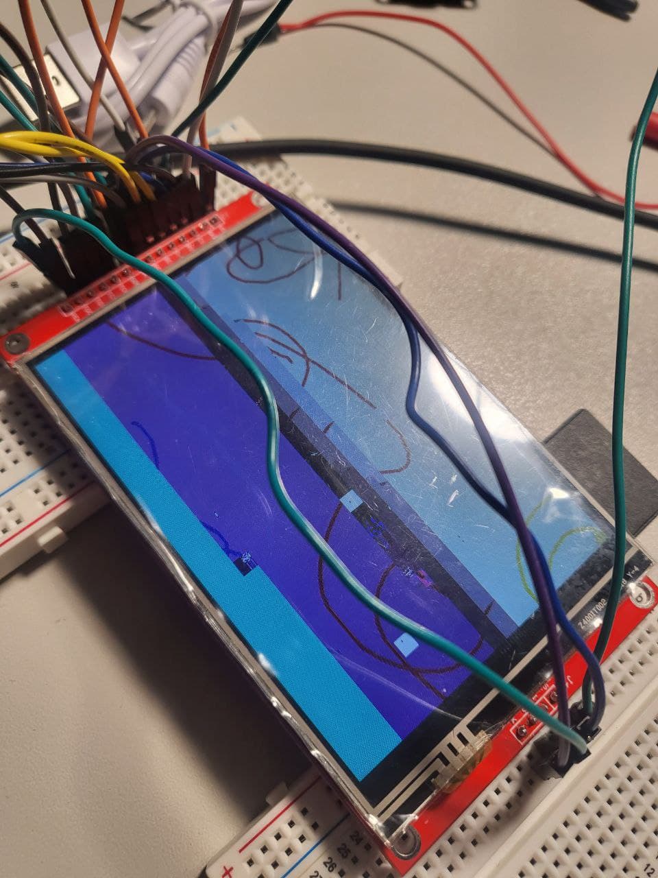
I’ve done a modification to a script taken from here https://www.xtronical.com/esp32ili9341/:
But this is what i see …upper part of the image was ok …the rest is just confusion ![]()
:
It’s the same as the Sunton display from Maker Fabs I linked earlier, which I have thoroughly considered. Nice to hear that it is faster than the 7" display with the SSD1963 driver. However as the OP said, there are not a whole of pins left for external uses.
Does the display have enough pins to establish communication with another ESP32? UART and I2C would only require two pins, and if the communication speed between the boards doesn’t need to be ultra fast it could be a reliable solution. For industrial applications I would also think about RS485 communication but I have no clue on how to do that…
1 Like
There are a few 4pin connectors on the PCB. I see one with UART+USB, one with SPI, one with GND, +5V, RX, TX and one with GND, +3.3V and 2 IO pins.
Nice! The RX & TX pins could be connected to a MAX485 and that way have RS485 serial communication between the display and another ESP32 or other microcontroller. Great for noisy environments.
Any updates on the board? I bought the Sunton 800x480 Display, one 5" and another 7". Both are very responsive and nice witht the widgets example. However, running some of the squareline studio examples like 3d_printer_v2, audio_mixer or even Smart_Gadget don’t work well at all! Very slow and in some cases I can’t even switch between screens. Am I seeing the limitations of the ESP32?
Hi,
I have a question about esp32s3, seems it can be easily used with LVGL, does it be good to use without LVGL?
Thanks
What UI library would you use if you use it without LVGL?
1 Like
I used TFT_eSPI.h for a while till met esp32s3 and seems lot of info. that used LVGL, wonder if ESP32S3 any special?
The Sonton ESP displays are RGB I thought?? Those displays would not work using the tft_espi library because that library doesn’t have support for that bus. The Arduino_GFX library does but it is using spi in a hackish way to do it and there is no support for DMA memory and that is a HUGE performance impact in a bad way.
1 Like