I started working on a project of making an ESP32 devkit that has a display attached. What I wanted no one seems to make. Here are the build specs.
4" IPS display with a monster resolution of 480x800. bright back lighting (6 LEDS)
i8080 8-bit parallel display interface
touch screen
ESP32-S3 8MB of octal SPIRAM and either 8MB or 16MB of flash storage
input voltage range of 5V - 24V.
3mbps UART to USB
USB-C
5V power supply
dual 3.3V power supplies
reset and boot buttons that can be accessed via a pinhole in the case
No extra fluff, no audio, no camera nothing like that.
thin design with the ability to add on without making it thicker.
That last item is the thing that doesn’t exist on any display I have found. All of the displays I have found have the pin header sticking straight out the back of the board or they have it edge mounted and the board on the back is the size of the display. I don’t want to have a 4" display that ends up being 2" thick if I only want to add a couple of things to it.
5V supply is not used by the display. it is there for anything added on. It has a 1 amp capacity
i did 2 3.3V power supplies. one powers the ESP32 and the other powers the display. The second supply is broken out and accessible by an add-on board just like the 5V supply. There are 2 voltage inputs. One is for a constant and the other is for either switched or constant. if the switched input is powered it will automatically power up the constant side but not vice versa. Super useful for automotive applications where switched is a must but keeps its usefulness outside of a vehicle as well where only a single power source is used. In a switched application the add-on board would have a voltage divider connected to the switched power and to an exposed pin. This would allow the user to put the ESP into sleep when there is no power on the switched line. The same pin get used can be used to wake the ESP when voltage is seen on the switched power.
All pins that are not being used are broken out. A total of 13 pins. The touch interface uses I2C and I broke those out as well even tho they are being used. Additional devices can be connected to the I2C. Almost all of the pins that are broken out are connected to the ESP32’s internal ADC.
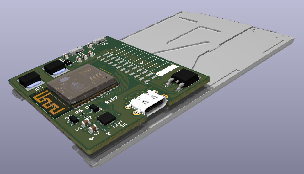
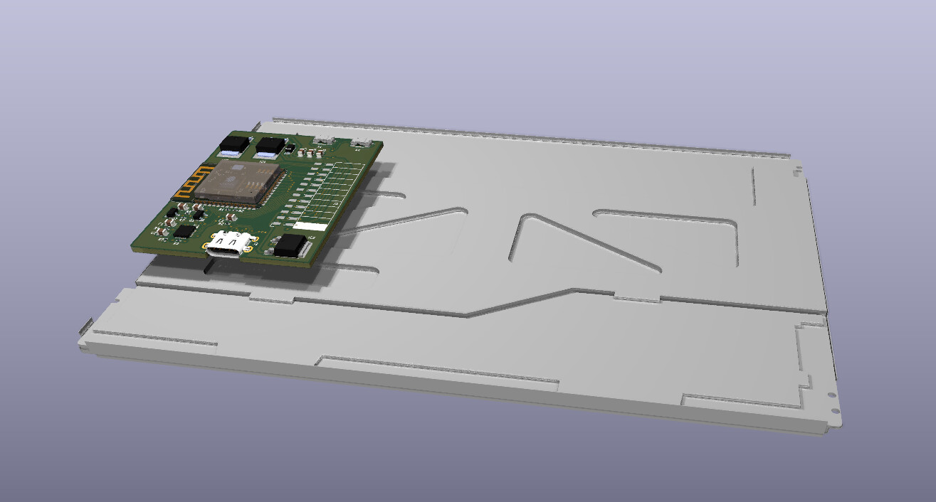
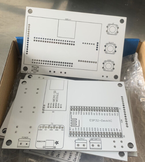
As you can see in the image the board on the back only cover 1/2 of the display this leaves quite a bit of space for an add-on board to get attached. I also have the connector for the display connected under the board instead of on top. While this did add a little thickness it allowed the footprint of the board to be smaller. The display chimes in at a tad over 8mm (~5/16") thick.
The tactile push button switches for the reset and boot are edge mounted. The USB as well. so unless something really bad happens it would be next to impossible to have them pull away from the board. The edge of the board is right up against the back of the switches and the USB. This also kept the thickness down as well.
The tracer lengths going form the ESP to the ZIFF connector are short . <= 6mm (1/4") in length. I used tracers for the power supplies that could handle 4 times the amount of current the supply is rated for.
I fear the ESP32 may be underpowered for most applications with a 800x480 display. It will be fine for more or less static screens but don’t get your hopes too high for animations or anything that requires frequent updates.
I made a board based on an ESP32-S3 with a 480x272 display. A difference here is that my display is controller-less (i.e. needs periodic refreshes of RGB data from top to bottom the whole time), which the S3 can handle natively via DMA (two frame buffers in SPI RAM). That’s not what makes it slow though… the slow part is the rendering of the graphics into the draw buffer. As soon as I have anything moving (such as dragging an object on the screen), the frame rate drops to around 5 fps, even if the changed area is not that large. Your resolution is about 3x as high, so I would expect it to be reeeeeally slow… unless there is something very wrong with my firmware - so I am curious. Let us know how it goes.
Now I had the same kind of experience with an ESP32-WROVER-B. Your issue is the lack of GRAM and the constant need to update the display. you are talking a frame buffer of 261,120 bytes. You would need 2 of them that size in order to get the benefits of using DMA memory. and even then LVGL having to redraw the entire display every single time is going to take time to do…
The ESP32 doesn’t have 522,240 bytes of DMA memory available onboard. it would end up using SPIRAM and that is going to slow things down. even more so if you have the version that has quad SPI and not octal.
it took me a while to fix the performance issues when I was using the WROVER-B
That display is 480x320 and it is being run by a WROVER-B with 4mb of quad SPI ram. 2 small DMA frame buffers that are 38,400 bytes in size (1/8th the size of the full display.) The WROVER-B doesn’t have DMA memory in SPIRAM only in the on chip memory .
You need to see how long it takes your code to run between calls to lv_timer_handler
I ended up removing lvgl’s handling through the use of lv_timer_handler and implemented my own way of doing redraws that doesn’t use timers or interrupts and I am able to have LVGL update immediately after I change something.
Perhaps the Sunton displays are what you are looking for? Maker Fabs example
I am also looking in the market for 480x800 display, though larger size (5 or 7 inches), that works with a ESP32-S3. However since in my project I also require the ESP32 to read data and perform control, most of the commercial boards are useless since they lack a lot of pins.
So one recommendation I would give, if you build this board, is to add some pin headers for the available pins
As for my research on a display that works with the ESP32, so far I set my eyes on the popular 7 inch display by “buydisplay”. Hopefully I can have the ESP32-S3 drive the screen with LVGL, while still having computing power and pins for other tasks.
///
edit:
woops I didn’t read completely and inferred stuff. The design is excellent and I would only hope you could make a similar design for the larger 5" and 7" 480x800 displays
could easily be adapted to a different display. if the pin out of the ribbon is the same it would simply be a matter of changing the display to a different one. The display is connected to the board using one of those ZIFF connectors so not a permanent connection.
If the pin out is different it wouldn’t be that hard to change the board design
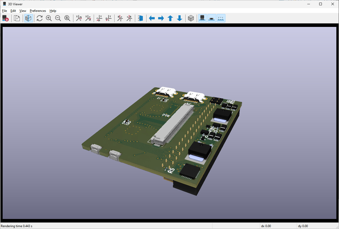
And here it is. updated for that display you linked to. I changed all of the tracers to go where they need to. There is no access to the font chip or the SD card as that would eat up pins. with the S3 having up to 16mb of flash there is no real reason for the SD card or the font chip use.
This is set up for use with a cap touch screen not a resistive.
Awesome! So if I am getting it correctly, this is a module that would fit the display PCB modules (the ones that already have the screen driver + touch driver).
Any plans for in the future having the ESP32, driver (e.g SSD1963) and touch screen driver (e.g. FT5206) all in one module? This would be very cool since then thinkerers could build their own versions of the S3 screens sold by Sunton by using the devkit PCB (with appropiate drivers) + a bare-bones display from BuyDisplay + whatever extra components they’d like to add.
This board I am going to make is specific to a display. The reason being is the manufacturers of the displays don’t use the same pin outs. The hard thing with a 7" screen is locating one that supports the i8080 interface. at 7" you start seeing mostly RGB and MIPI display connections. The ESP32 doesn’t support the MIPI connection natively. There is a bridge that can be used which converts i8080 to MIPI. RGB just uses a whole lot of pins plain and simple. 8 pins for R, G and B and then additional pins for VSYNC and HSYNC. and some others as well. If using an RGB display that supports RGB565 or 16bit color you can shrink the number of pins being used down by 8 pins but it is still a lot of pins that end up getting used.
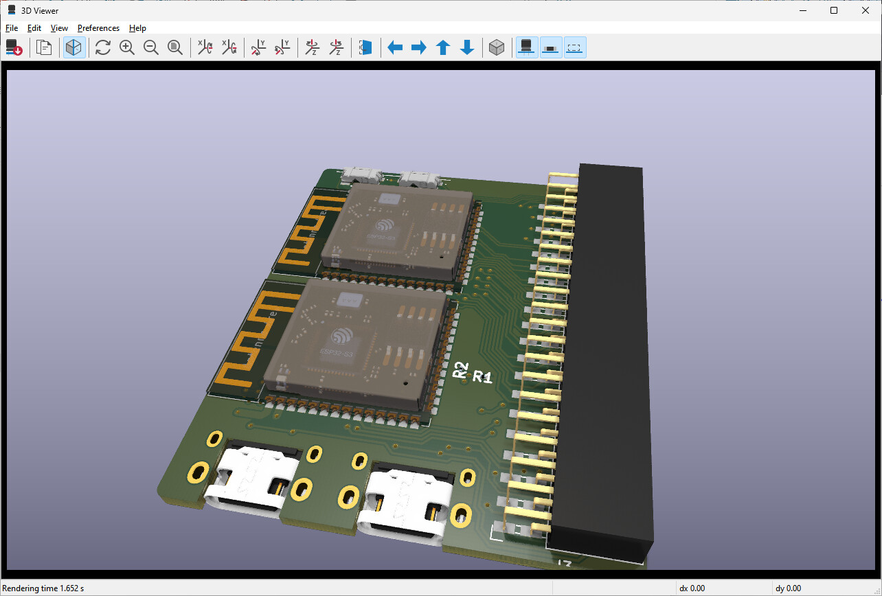
I have thought about building a dual ESP32 dev board so one ESP would be for IO and the second would be for the display so an RGB display could be used but LVGL doesn’t support 24 bit color out of the box and it would have be set to 32 bit color and the alpha byte would have to be stripped off in the flush function.
I think the ESP32 would be able to update something like a 7" with a resolution of 1024 x 768 so long as it wasn’t doing anything other than the display. There would have to be some alterations made to utilize both cores and some kind of a mechanism to allow the 2 MCUs to communicate with each other.
Running 2 ESP32’s would be cheaper than adding an IC to expand the number of digital IOs and another IC to expand the analog IOs and yet another IC to add PWM outputs. I2C would have to be used because SPI would take up too many additional pins. one CS for each of the 3 ICs and the original 3 used for the SPI itself totaling 6 pins needed on top of the 30+ used by the display.
an ESP32-WROOM-1-N8R8 (8mb RAM and 8mb flash) has a retail cost of just under 4.00 USD. a 4 channel 12bit ADC has a retail price of about 4.00 USD. It’s cheaper to go with a second ESP32 because that is just the ADC, not the digital IO and the PWM.
I would say that already with a screen like the ILI9488 3.5 inch (480x320 Pixel) the refresh rate is almost at the limit with an ESP32 wroom 30 Pin.
If I were you I would limit myself to making an STL containing ESP32 and screen, or a PCB with the connection traces between ESP32 and the screen.
Combining 2 ESP32 together seems to me a more complicated thing (and perhaps with the wifi connection you save some connection)
Here you can see a project I made for a table clock with wind signal (code included).
HI
@gabriele_ponte
how do you have the esp32 connected to the display??
I ask this because it could be what you are preceiving asmaxing out the sped of the ESP… also have you changed the way LVGL updates the display or have you left it as is? do you have any other code running on the ESP?
an ST7889 driver IC has a clock of 50mHz for i8080 and you can go to 80mHz for SPI. SPI is able to send 1 bit at a time so you would get a speed of 80Mbit a second. with i8080 you get 50mHz which is 50Mbit but then you multiply that by the number of lanes. so a 16 lane has a speed of 800Mbit, 10 times faster than SPI. That is a hell of a speed increase but at the cost of using a lot of GPIOs on the ESP.
That is theoretical and not real application. SPI is going to be slower as is i8080. The difference in speed should still be about the same…
@pllagunos
The touch driver ic and the display driver ic are actually built into the flexible PCB that comes out of the back/side of the display. So all that has to be done is the routing of the GPIOs from the ESP to the connector for that flexible PCB. The display you posted has a rigid board on the back that has the driver ic for the display and touch and it also has an SD card reader ad well as a font chip. Those additional components are the reason why they used a rigid PCB instead of a flexible one.
You can find the connections I used in the .Zip file (or at the end of the youtube movie) and also the LVGL and TFT_espi configuration I used (to be precise, I used LVGL version 7.11).
The connections use 8 pins of ESP32 or 9 if you want brightness correction via software.
I didn’t try to use larger screens because the 3.5-inch size was enough for me, but I saw that with this size the refresh rate was still decent.
HI
if it’s an 8 wire connection it’s gotta be 4 wire SPI.
the speed in which the display is refreching is not a limitation of the ESP32 or LVGL but instead is a limit of the display. If you have a grip of unused GPIO pins on the ESP32 then you could run a display that can do an 8 lane i8080 connection. You would need 8 pins for the data lines, 4 pins for the control lines, a pin for hardware reset (optional), another for the backlight (optional), the 2 pins for the data from the touch panel, hardware reset for the touch panel (optional) and an interrupt for the touch panel (optional)
If you don’t use any of the optional pins you would need a total of 14 pins, 6 more then you are currently using. 8 lane I8080 would be 5 times faster than SPI. still a respectable boost in speed. On the ESP32-S3 there is a lot of pins and I would be surprised if you are using them all. You can connect a 16 lane i8080 display and still have 3-4 pins left for use on other things.
I wanted to do a 16 lane connection to a display that has a really high resolution of 800 x 640 for a 4" display with 24bit color. It would look really amazing. Thing is I need more than 3-4 GPIOs left over. I need to have 10 additional pins most of them being analog.
Using 2 ESP32’s shouldn’t be too difficult to do. I can use I2C to send data from one that is handling everything other than the display. assign id’s to the various widgets in the display so the data that is sent would be the id and then the data I want displayed. the other ESP I would run LVGL on to handle the display. modify do away with the timer related bits in LVGL for refreshing the display and reading the touch interface. The only thing that would be getting done is reading the touch, reading the I2C for data to update the values in widgets and updating the display.
I have not published the code anywhere. The simple version of what I did is delete the timer for the display refresh and I call the refresh callback periodically in my code. I handle the animations myself and I also monkey patched some of the code for how the touch screen is handled so it gets priority.
almost there. dual ESP32-S3’s. One for sensors and the other connected to the display using 16 lanes. I2C used to connect the 2 together. If you really think about it how much data would get sent between the 2. Not all that much really. SPI can also be used to communicate between the 2 and also WiFi
I would definitely be interested in this! Would be great to have access to design files of the PCB, in case someone want’s to add more components to the PCB. For example terminals/connectors for sensors, amplifiers/optocouplers/whatever to have compatibility with things like thermocouples or just pins to connect common modules.
I made a PCB that has a ESP32 driving a small 2.8" TFT display on the front and has all the connections for sensors in the back side of the PCB.