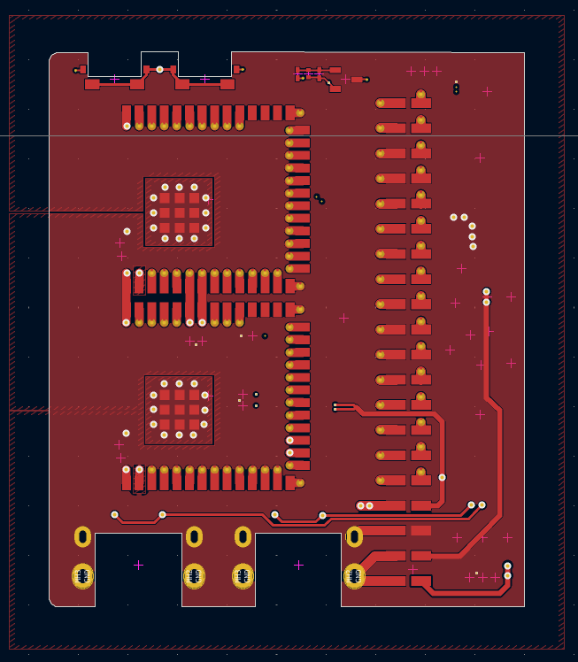
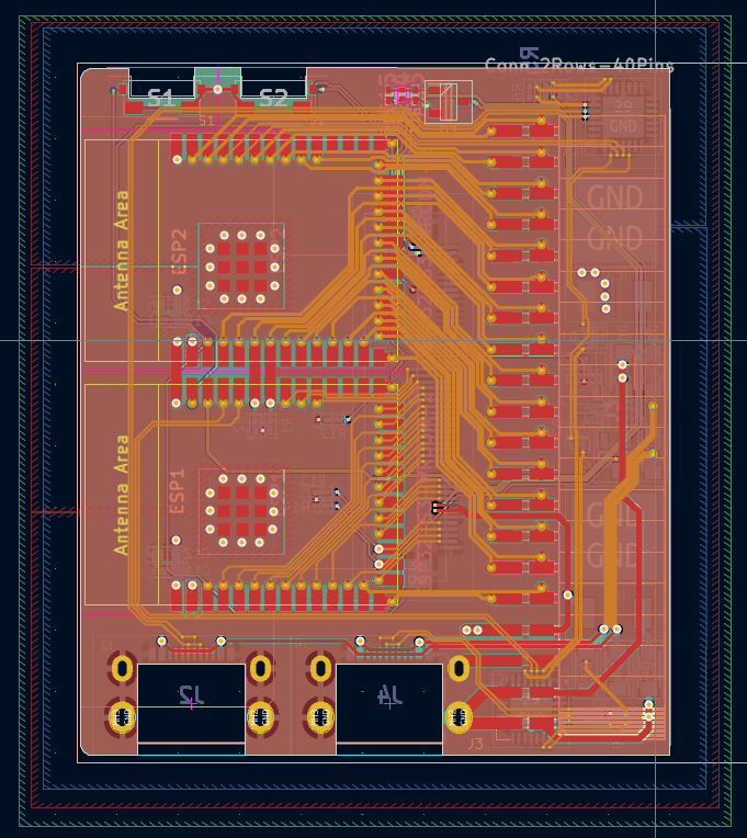
I actually am working on it now. I changed up the design. it now has a 4 layer PCB. 2 ground planes a power plane and a signal plane. the layers are as follows.
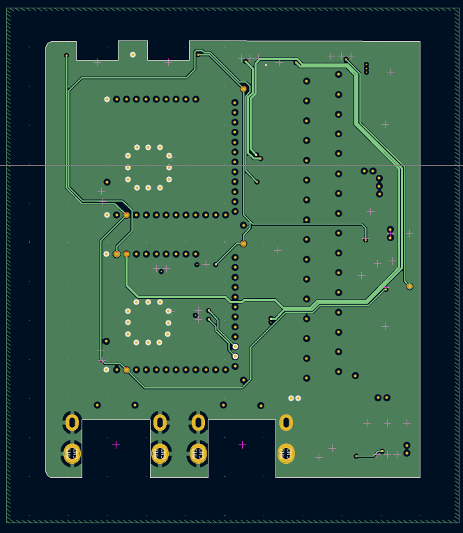
top: power
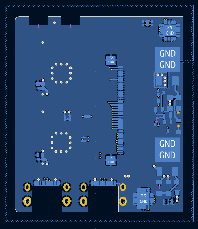
second: ground
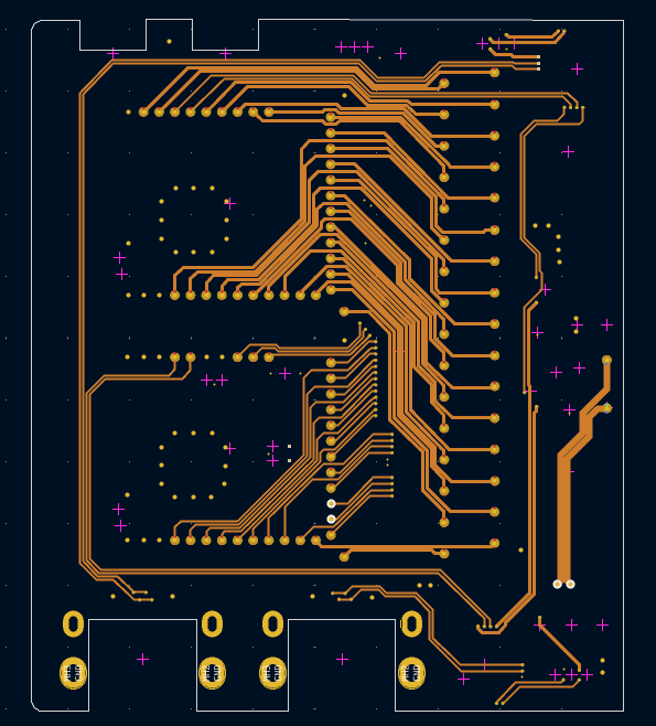
third: signal
bottom: ground
I stuck the signal layer between the ground planes to eliminate EMI getting to the signal wires. This will reduce noise on the signal lines.
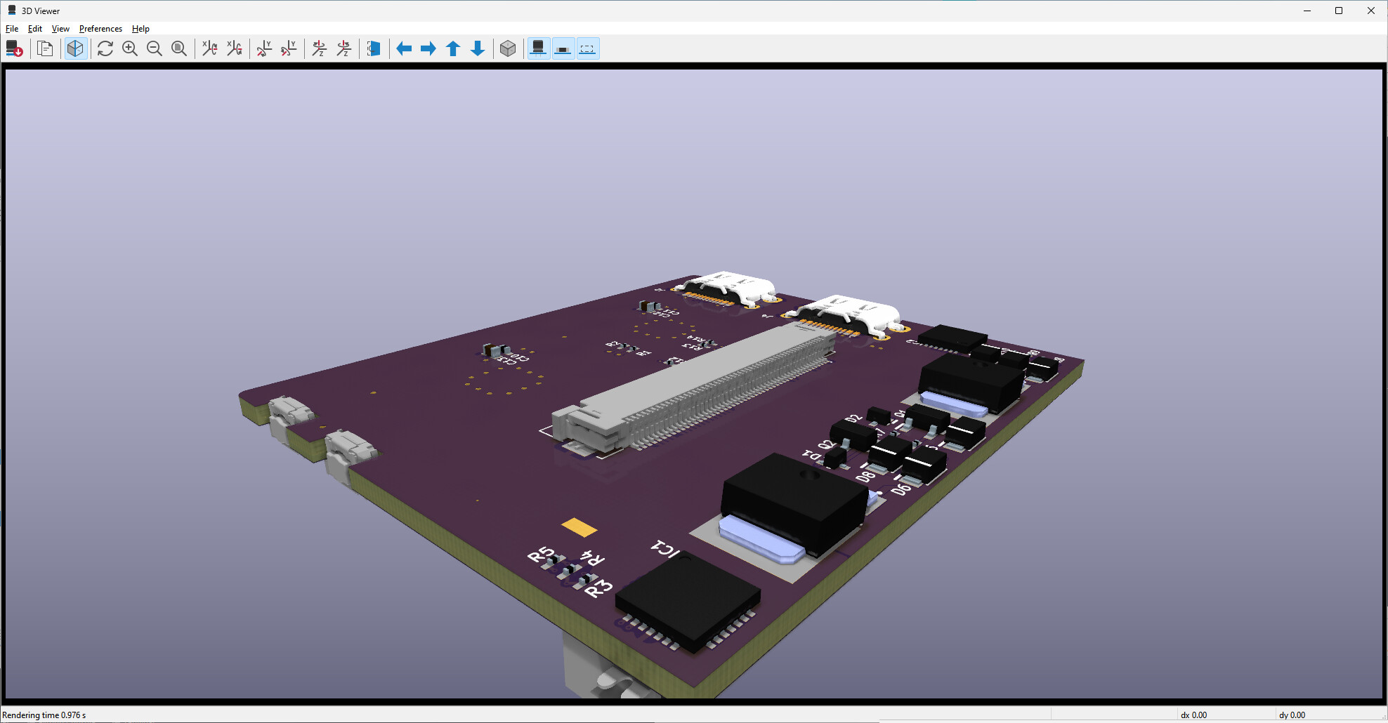
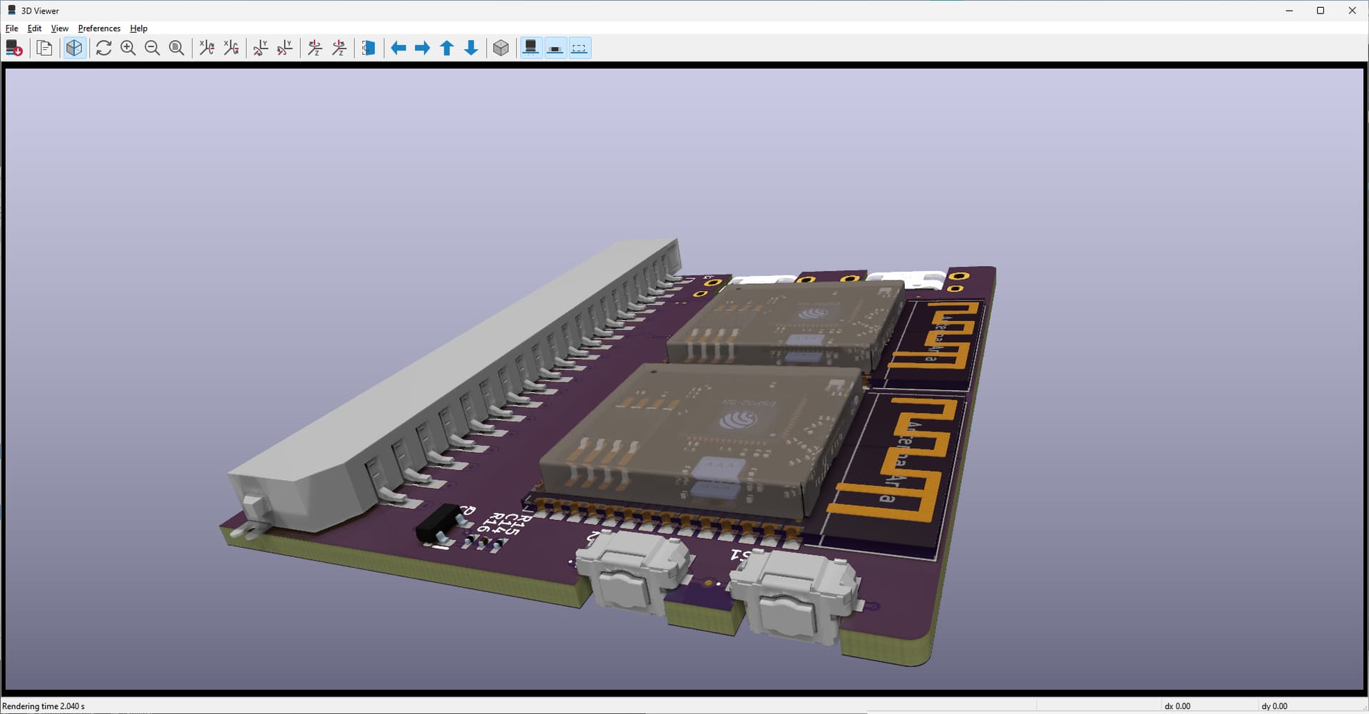
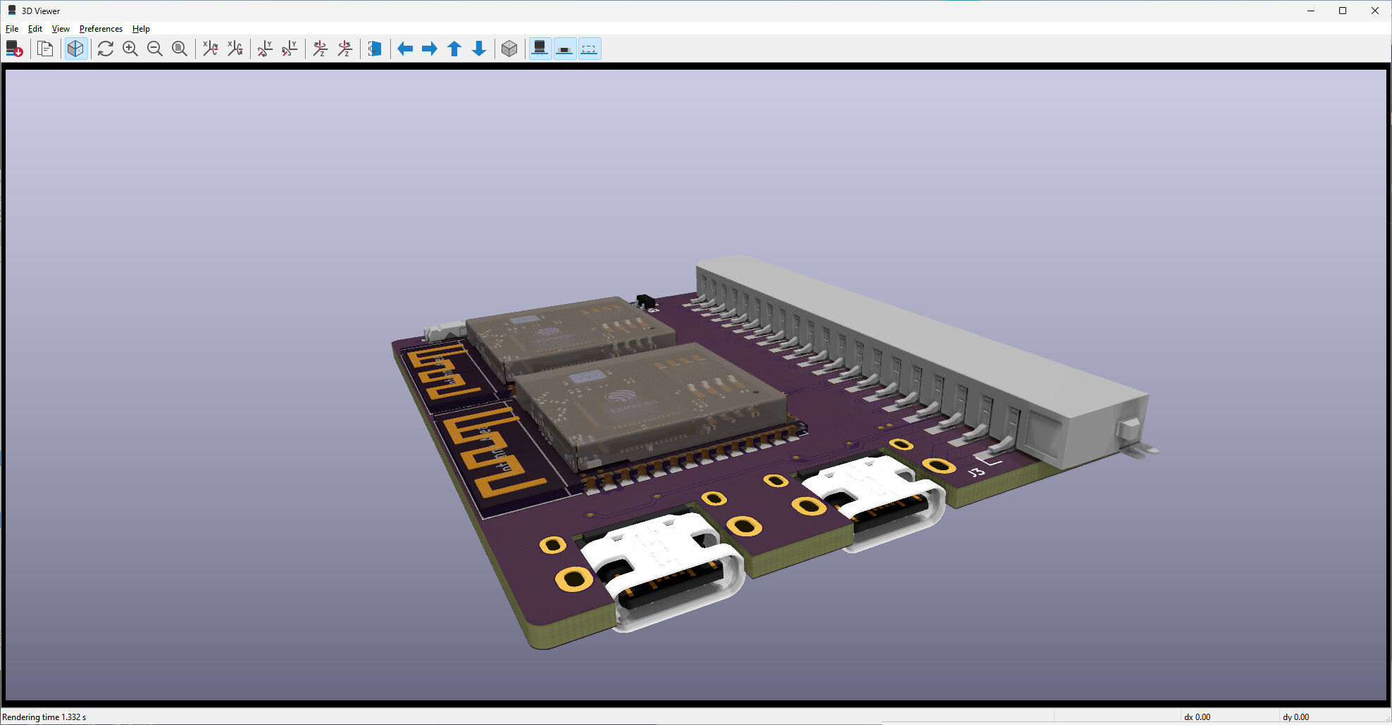
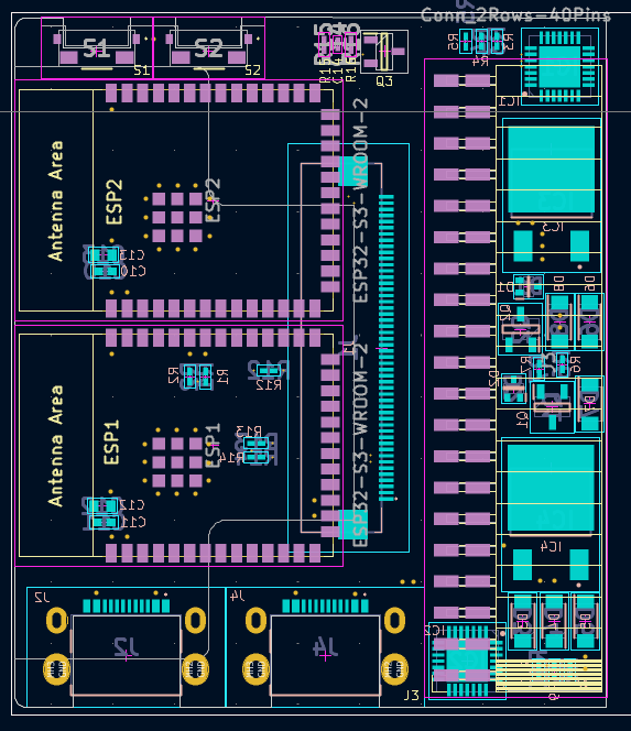
Every available pin is broken out to a pin header. the ESPs are connected together via a dedicated I2C. That I2C is also broken out. The touch has it’s own I2C. display connection is for a 16 lane i8080 interface to one of the ESP32’s.
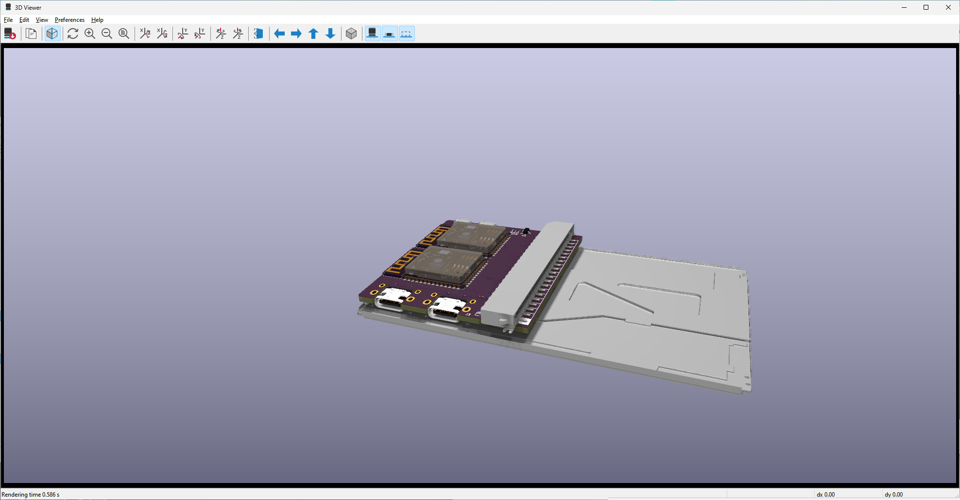
Whats cool about how the board is designed is you see next to no traces on the board. I am also using blind vias and all of the vias for the ESP’s are under the ESP so you won’t see those either. The overall board measurements are 1.9" (48mm) x 2.2" (56mm) x 0.35" (9mm). That’s without the display. The display adds 2mm for an overall thickness of just a tad under 7/16" (11mm) thick. The board only covers 1/2 of the back of the display. This is important because it leaves room for an add on board so the thickness can be maintained depending on the design on the add on board. There is 2mm of space between the board and the display so there is room to have components on both sides of an add on board.
the display I am going to use has a crazy high 54,852 pixels per square inch. I think the ESP is not going to have an issue driving this display. It’s not going to be able to do video but it should have pretty decent transitions and animations.
One other thing is the ESP’s I plan on using are going to have 8mb of flash and 8mb octal spiram on each of them.
I haven’t gotten any fabricated yet. Been really busy. I need to go over the PCB design and make sure everything is how it should be. Last thing I was doing on this was looking for a way to make a connection between 2 PCBs that would be a really solid connection. something that was really small too.
In case anyone is looking for performance that can play video at 24+ fps, a Teensy Micromod with 8 bit 8080 bus on an ILI9488 can get almost 75fps with DMA and two half screen sized buffers:
There is also a version of the code for a Teensy 4.1 that does not support DMA but also shows very good results, can even do 16 bit 8080 (need to add it to the library)
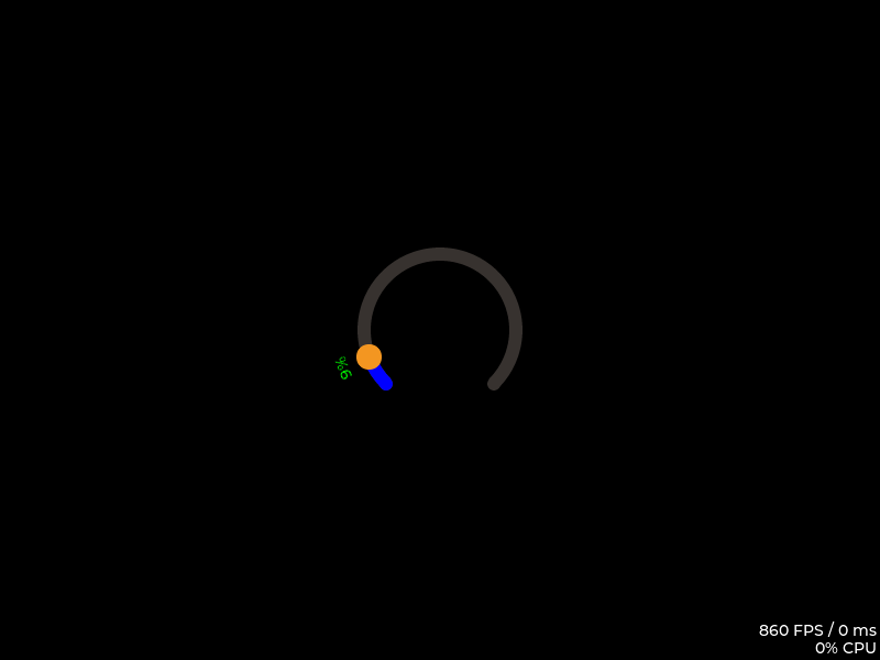
I am going to tell you right now that FPS number is wrong. It is almost double what it actually is. In the current LVGL the way the FPS is calculated is including when there is nothing that ever gets written to the display. This skews the measurement big time. The measurement can also be altered if calls to lv_refr_now are done and there are no updates that need to be done.
and this is after a partial fix of how the math is being done. The issue with the counting of frames when nothing ever gets rendered has not been fixed.
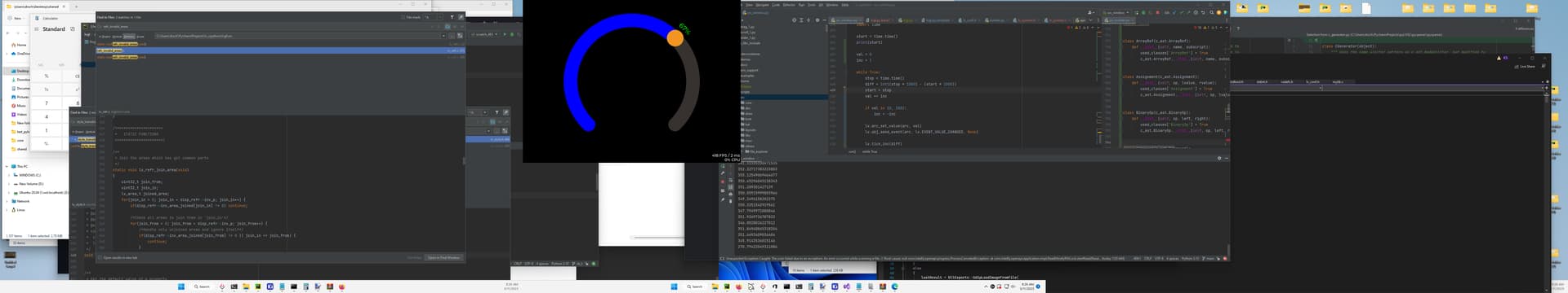
I didn’t take a screen shot of what the numbers are when it is fixed But it is the same as what you see behind that last image on the bottom right of the LVGL window. You can see the numbers are a lot closer but still not exact.They are almost identical but not exact. That is because LVGL uses integer math instead of floating point math and also because LVGL is using millisecond time precision. In the calculations that I had running nanosecond time resolution and floating point math was being used.
LVGL can report up to double what the actual frame rate is. The higher the frame rate the larger the error that is seen.
Good morning!
As you i’m searching something (5" touch ) on the market with at least 20 pins to my project!
How is it going your board development?
I’m completly noob in this stuff…but i hope that your board will be a good chance!
I’ve implemented a software on Arduino 2, but for a lack of power, i need to switch to ESP32 board and use the TFT_espi library…hopefully can be imported into your board easly!
If you are looking for something that has speed I would opt for using a custom written driver and not use the Arduino or any of it’s libraries. This is due to the additional layers of code that has to run in order to forward Arduino function calls to the ESP-IDF.
I have not had any time to do much in the way of working on this board. I have to go back over the design and make sure everything is done the way it needs to be. The problem with a lot of displays out there is the lack of information on the back lighting and if resistors are needed and what their values need to be. This is all dictated by the number of LEDs and how they are “wired”. I don’t have a lot of experience with the companies that manufacture prototype boards cheaply. My concern is quality dealing with the really small buried vias and the board being a 4 layer board. I don’t want to spend 500 bucks on a few prototype boards only to find out the quality is not up to where it needs to be.
The last prototype boards I had made were for a simple project and I used all through hole components with a 2 layer board which is pretty easy stuff for pretty much all PCB manufacturers. With the board being a 4 layer and vias not being visible on the outer layers there can be hidden problems that cannot be fixed.
depending on what you are connecting there are several things you can do. You can add an IO expander that does digital in and out. works over I2C. this is good for simple on and off type of things. If you need to read analog sensor values then you can use an ADC expander again it runs on I2C as well. If you need to have PWM support there is a plethora of 8 channel expanders available for that as well. Also runs over I2C. So you really only need 2 extra pins off of the ESP32 for the I2C. This is a viable solution if speed is not a necessity because the I2C isn’t the fastest thing in the world.
I suggest staying with using the ESP32 as it has a feature rich SDK that is well documented and easy to understand. The single SDK works with the majority of the different “flavors” of ESP32’s that are available.
If speed is a non issue then use an SPI interface. Just be aware that it will lag/jump some when doing any animations or scrolling. This can be reduced by using 2 frame buffers that are allocated in DMA memory. If you use the ESP32-S3 with a display that uses SPI then you should not have any issue with having 20 pins available.
What do the 20 pins need to be available for? analog reading?, analog writing? digital read?, digital write? knowing how many pins are being use for what kind of input/output would be really helpful to have.
This example is a project I am working on. It is an ESP32 -WROVER-B… It has very little DMA memory available so I am running 2 really small frame buffers.
That is also written using the MicroPython Binding so there is going to be a performance impact from that alone… The extra RAM is also using quad SPI which is 4 times slower than the S3 with octal SPI RAM.
In that example The program is reading 2 temp sensors, a current sensor, 2 pins for voltage. one pin for fault detection from a power supply. another pin is an output for sleep control of attached circuits. and there are 2 pins used as PWM output to control the speed of a 50amp DC motor and a 20amp DC motor. There is quite a bit of float math involved for reading the temperature sensors.
I did have to do some manipulation to how the task handler works in order to get the refresh speeds I wanted to the display. Nothing too crazy tho.
Thanks for your answer, i’ve just bought the following boards
hopefully i will be covered on my needs, and i remain with ESP32 also!
Bodmer from TFT_espi suggested also a Nucleo dev board (STM32F446 or STM32F767), but wasn’t the easiest device to work with!
About the question for my pin use i’ve the following stuff
10 relays (probably 5/6 solenoid valves, 1 heater, 2 for pump (to drive pump in both directions, 1 for future use)
3 pins for the L298n motor driver (1pin Enable, 2 pins motor run)
2 pins for the temperature sensors
It’s a very simple project, i need to manage 5/6 solenoid valves that are opened to move back and forward some liquids using a single pump.
The temperature of the liquids (2 different places) need to be checked before start moving the liquids, and a little motor need to agitate a container with the fluid during all the process.
Unfortunally using the Adafruit_GFX there was some glitches during the update of the screen when the percentage was going on , with also a bargraph…so also for a much power platform, and the possibility to create the structure of the software using the GUISlice builder for a different display size…i’m moving from Arduino 2 (amazing amount of pins…no problems at all…) to ESP32 S3 (the board i’ve linked above…
OK. so you need a 12 port IO expander is what you need. something simple that can provide you with digital IO pins for the relays. There are a lot of I2C relay boards available to do what you need. You can either get boards that use mechanical relays or you can go solid state depends on your needs/preferences. the PWM for the motor speed controls you can either use PWM pins on the ESP or optionally you can use an PCA9685 PWM expansion board. don’t let the word “servo” trick you. It provides pins for the power and ground to control servos conveniently but the PWM output pins can be configured to drive motors just as easily as servos.
The reason why I thought of using dual ESP32’s is because you can roll everything into a single “expansion” board. the second ESP32 acts like an ADC expander, a digital expander, a PWM expander all in a single package with a price of 10.00 to 15.00 USD. where as if you add a the 3 mentioned expanders you are looking at 10.00 USD each for a total of 30.00USD plus you have the added wiring and space used for those 3 additional boards.
Makes more sense to dedicate an ESP32 to handle the IO and another to handle the graphics and connect the 2 together using I2C
I’ve a question for you, about the relays…i don’t know why the solid state that i’ve bought are not working…the mechanical works perfectly fine…the wiring is the same…really strange!
So i can drive the motor directly using the pins of the ESP?Also i can invert the rotation?I’ve programmed my motor with a timer that for Nseconds the rotation is clockwise and then go in opposite direction…
Sorry for the super late response, but i wan’t able to make more than 3 post on a thread (as a beginner on this platform…)
you have to be careful with solid state because some of them are made to work with AC loads and others with DC loads. Some can also have load threshold that you have to pass in order for them to work. You need to read up on the type you have. Usually if it is a mosfet type of solid state relay then it is going to be for DC and if it’s an SSR then it will usually be for AC
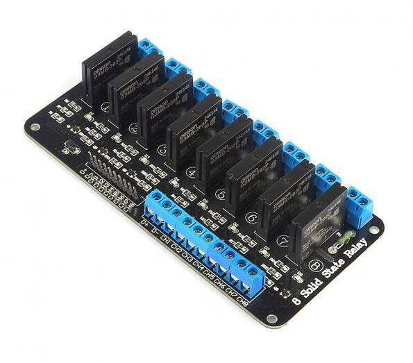
This is an SSR relay board and is designed to switch AC voltage. It’ not I2C either but it shows you what an SSR looks like.
5 volt trigger.
designed to turn on and off AC power not DC.
not I2C
What you are trying to do is reduce the number of pins you are using. you need an I2C board
What are you trying to switch with the relays? is it things that use AC power or DC power?