Display + touch not displaying anything on ESP32

Hello, I am new to LVGL and Micropython as well, first time using it and I need help.

My problem is that when initialized, ili9341 display and xpt2046 touchscreen do not display anything. I’ll go over my setup.

I am trying to connect this display to the ESP32, and I am doing so connecting the pins in the photo to the default pins that are declared in lv_micropython’s README.

I followed the example in the README, in a Ubuntu VM, opened a PuTTY session, imported and initialized both display and touchscreen in a Micropython prompt, with seemingly no errors. Messages displayed were:

Single buffer
II9341 initialization completed
Enable backlight

for display and nothing for xpt2046.

Then, I copied the code below that example in the README, which looks like this:

# Create a screen with a button and a label

scr = lv.obj()
btn = lv.btn(scr)
btn.align_to(lv.scr_act(), lv.ALIGN.CENTER, 0, 0)
label = lv.label(btn)
label.set_text("Hello World!")

# Load the screen

lv.scr_load(scr)

But after that, screen just displays white (nothing changes).

What am I doing wrong?

Did you call to lv.task_handler and lv.tick_inc?

At first I didn’t. Now I put in my code the following lines at the end:

while True:
    lv.task_handler()
    utime.sleep_ms(5)

which apparently resulted in a timeout error from ampy (as that’s what I am using to run the file in the board).
I also looked at the docs for tick_inc() but couldn’t understand where to place it. Could you please instruct me in doing so?

You are going in the right way.
The tick_inc(5) should be placed after task_handler, in the same while loop.
To avoid ampy crash, you should print something(like print(".") ) every second. I think it has some timeout to prevent device blocking.

Hi @GianK128 !

It’s not clear to me which display exactly you are using. The link you sent is for RPi_TFT_Connections.png but it’s not clear what this board is, or even if this is an ili9341 board.

Did you try your board with some other library and the same wirings? Could be useful to make sure the board isn’t defective.

For testing, try to initialize only the display, see if it works without the touchpad.

Are you using the latest version of lv_micropython from GitHub?

I don’t think this is needed, at least not on esp32 ili9xxx on latest version.
It should start the event loop automatically if it wasn’t started already, and the event loop would call lv.task_handler() and tick_inc.

First of all, sorry for my ignorance.

I did that. The program still runs, but the output of the screen is still just white. I think the problem may be in the display itself, going with what @amirgon said.

I borrowed this screen from someone I know and couldn’t identify it. The picture I shared was the one I found the closest to the board I have in hand. Now, doing some more digging, I found this one which I think is exactly the one I have, and it actually has a ili9486.

Also, for the lv_micropython version, I cloned it like a week ago or so, so I think I could’ve missed some file updates.

So, my question now is does the ili9488 class work for this display as well? I could try doing that. I will also try looking if I connected wrong the display looking at the pinout in that page.

From that family of display controllers, only ili9341, ili9488 and gc9a01 are supported today in lv_micropython for the ESP32.

The ili9486 might be close enough to ili9488 so you could try using the same driver, I’m not sure. You need to check the datasheets. Possibly, You would only need to change some init values.

Hi @GianK128,
What I had to do was first deside on the pins I wanted to use for LCD and touchscreen and SD card if your using it so they don’t conflict. (im using the ili9341 lcd) Then I updated the file:
lv_micropython/lib/lv_bindings/driver/esp32/ili9XXX.py

In the ili9xx and also in the ili9341 method/location so they looked something like this for me:

ili9xx section:
	miso=12, mosi=13, clk=14, cs=15, dc=26, rst=27, power=-1, backlight=33, backlight_on=1, power_on=0,
        spihost=esp.HSPI_HOST, mhz=40, factor=4, hybrid=True, width=320, height=240,
        colormode=COLOR_MODE_BGR, rot=LANDSCAPE, invert=False, double_buffer=True, half_duplex=True, display_type=DISPLAY_TYPE_ILI9341,
        asynchronous=False, initialize=True
ili9341 section:
        miso=12, mosi=13, clk=14, cs=15, dc=26, rst=27, power=-1, backlight=33, backlight_on=1, power_on=0,
        spihost=esp.HSPI_HOST, mhz=40, factor=4, hybrid=True, width=320, height=240,
        colormode=COLOR_MODE_BGR, rot=LANDSCAPE, invert=False, double_buffer=True, half_duplex=True,
        asynchronous=False, initialize=True

I updated the touchscreen file so that it would work with landscape mode:
lv_micropython/lib/lv_bindings/driver/esp32/xpt2046.py

mine looked something like this:

		self, miso=-1, mosi=-1, clk=-1, cs=25,
                spihost=esp.HSPI_HOST, half_duplex=True, mhz=5, max_cmds=16,
                cal_x0 = 3948, cal_y0 = 242, cal_x1 = 423, cal_y1 = 3783, 
                transpose = False, samples = 3

Then I compiled the everything so when running lvgl code on my esp32 all I have to add to the beginning is:

# Import libraries
import lvgl as lv
from ili9XXX import ili9341
from xpt2046 import xpt2046

# Initialize drivers
lv.init()
ili9341()
xpt2046()

# then add lvgl code here

If you don’t update those files then you can test by adding your parameters/wiring when initializing the driver like:

# Import libraries
import lvgl as lv
from ili9XXX import ili9341
from xpt2046 import xpt2046

# Initialize drivers
lv.init()
ili9341(miso=12, mosi=13, clk=14, cs=15, dc=26, rst=27, power=-1, backlight=33, backlight_on=1, power_on=0,)
xpt2046(miso=-1, mosi=-1, clk=-1, cs=25, cal_x0 = 3948, cal_y0 = 242, cal_x1 = 423, cal_y1 = 3783)

You also have to look at the file for your LCD if there are any special build instructions as for the ili9341 it notes you have to compile with specific CFLAGS like:

* esp32 NO psram
make -C ports/esp32 LV_CFLAGS="-DLV_COLOR_DEPTH=16 -DLV_COLOR_16_SWAP=1" BOARD=GENERIC

* esp32 WITH psram
make -C ports/esp32 LV_CFLAGS="-DLV_COLOR_DEPTH=16 -DLV_COLOR_16_SWAP=1" BOARD=GENERIC_SPIRAM

And after you compile you have to look at the instruction for uploading the firmware to your esp32. when I tried simply uploading the firmware like before it was not working. It only worked when uploading like the documentation mentioned.
EX:

/home/esp32/.espressif/python_env/idf4.2_py3.7_env/bin/python ../../../esp-idf/components/esptool_py/esptool/esptool.py -p /dev/ttyUSB0 -b 460800 --before default_reset --after hard_reset --chip esp32  write_flash --flash_mode dio --flash_size detect --flash_freq 40m 0x1000 build-GENERIC_SPIRAM/bootloader/bootloader.bin 0x8000 build-GENERIC_SPIRAM/partition_table/partition-table.bin 0x10000 build-GENERIC_SPIRAM/micropython.bin

hopefully this helps, those are the things that gave me a hard time while trying to compile and upload the FW to my esp32.

1 Like

Hi, sorry for the late response. I didn’t have time to work on this until now. I’ll try recompiling and using the ili9488 class.
I will also take a look at the ili9486 datasheet, to see if there’s something that can be done if step 1 doesn’t work.

Thank you for your time. I’ll update if I manage something.

Hi, thanks for your detailed answer!

Seemingly, I had no problem building the firmware and uploading it to the board. I haven’t changed the files directly, I was declaring the pins when initializing the driver. Still, that last line could help me in the future.

The problem I have is that my LCD just displays a white screen. And it probably is related to the model of the display.

I have to recompile anyways, so thank you again for the answer.

Ok, so I tried to use ili9488 driver after recompiling, and I am hitting the next error:

"Not enough DMA-able memory to allocate display buffer"

that is present in line 134 of ili9XXX.py file when trying to initialize the driver. It doesn’t matter if I have double_buffer set to True or False.

I am lost to what the cause would be, given that it did not happen the previous time.

The steps I followed to recompile were:

make erase
make -C ports/esp32 LV_CFLAGS="-DLV_COLOR_DEPTH=32" BOARD=GENERIC ESPIDF="$HOME/esp/esp-idf" deploy

Does anyone have any ideas as to what the problem is?

ili9488 has higher resolution than ili9341 therefore display buffer size is larger.
It’s recommended to use a board with psram (SPI ram), where Micropython uses it instead of the main ram leaving more ram for the display buffer. You would also need to build with BOARD=GENERIC_SPIRAM

You can also try increasing the “factor” parameter to higher values (8, 16, 32 or 64) to configure smaller buffer at the expense of performance.

Hmmm @amirgon has a good point, maybe that higher resolution display is only supported on esp32 devices with PSRAM. Try building the spiram version to see if that resolves the error even if you don’t a board with psram. It would be a good data point :slight_smile:

If you want to further test your previous FW build(s) I would buy a generic usb logic analyzer from from aliexpress for like $5 (or $15 from amazon) and install pulsview/sigrok on your linux VM (You will have to pass through the usb device) or windows machine. Then take a capture of your spi signals to see if you are getting any data.

The steps I took to build was:

  • Downloaded lv_micropython
  • Made changes to the lcd and touchscreen files
  • Downloaded the esp-idf
git clone https://github.com/espressif/esp-idf.git
cd esp-idf
git checkout v4.2
git submodule update --init --recursive
./install.sh
  • Took a snapshot of the VM to revert later!
  • While in the esp-idf directory set esp-idf environment variables
source export.sh 
  • Then compiled
cd lv_micropython
make -C mpy-cross
make -C ports/esp32 LV_CFLAGS="-DLV_COLOR_DEPTH=16 -DLV_COLOR_16_SWAP=1" BOARD=GENERIC_SPIRAM

Higher resolution is not limited to devices with psram, you can use smaller display buffer by increasing “factor” parameter of the display driver. But you might get lower FPS.

@saul could you recommend a specific logic analyzer you have good experience with?

@amirgon I’ve just need to look at SPI and I2C in the past so I just got one like this but from aliexpresss:

It can do more than just those two protocols but I don’t believe it supports analog measurements. Also I only used it on LInux/Debian with sigrok (need to install the driver from repos sigrok-firmware-fx2lafw)

Thanks for this link :+1:

But it says max sample rate is 24 MHz. Were you really able to capture the SPI bus of the display at 40Mhz? Or did you lower the SPI rate?

Hmm I didn’t think about the SPI speed. I only did some SPI captures when I was having some issues with the SD card. I don’t have time today but I can see if I can get a capture at 40MHz, tomorrow night. It might be able to capture at that rate but at a reduced capture time.

If it doesn’t work i can try reducing the SPI speed on the driver to 20MHz to see how that goes.

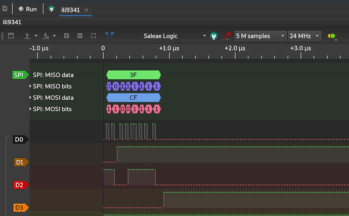
Ok so I did some testing today and yeah you can only go up to 24Mhz on that cheap logic analyzer. Not sure if its false advertising but I only got repeatable captures when setting the LCD driver up to 10Mhz (Analyzer sampling rate 24Mhz).
I.E.

import lvgl as lv
from ili9XXX import ili9341
from xpt2046 import xpt2046

lv.init()
ili9341(mhz=10)

So I wouldn’t expect this analyzer to be usable for devices faster than 10Mhz.

MOSI values seemed to check out with LCD driver:

under method:
static void tft_init(struct fb_info *info)

let me know if you would like the capture file to play around with pulseview :slight_smile:

Sorry, forgot to tag you guys @amirgon @GianK128 . Let me know if you have any questions.

Thanks for the infomation @saul !
10Mhz is still very useful for a cheap logic analyzer.