Create Phasor Diagram

@kdschlosser you are a bro!! Thank you man.
Yes, by vector i mean a line that starts at the origin of the graph (the circle center) and has 2 parameters:

  1. The vector magnitude (how long is the line)
  2. The vector angle (the angle that the line forms with another referring line, could be for example x-axis, but as you can see from the youtube video, the angle is between, the 0 degrees, -120 degrees and -240 degrees, just take a look at the video above so you can see it).

p.s.
If you will need any help in the future for some projects, donā€™t hesitate to ask me!

You are not going to have the ability to set the alpha transparency level of the background for this ā€œwidgetā€ This is due to a limitation in lv_canvas. I am going to render most of the widget only a single time in order to keep the performance up. The tradeoff is the loss of the alpha for the backgroundā€¦

If you tell me what operating system you are running on your computer I can compile LVGL so it will run on it using Python. This way you can prototype and see it running on your local machine. I can do it for the simulator but the API between the MicroPython port and the C version of LVGL are really on opposite sides of the planet so to speak. The binding I wrote for CPython is almost identical to the C API which would make it easier for you to port to C code.

I use windows 11, how much time do you think that will require me to translate in c? Are there a lot of lines of code?

For this no problem, will make it work in some way.
Thank you

If you are using Windows 11 then I can move the code I have written for MicroPython to CPython now. If I write the code for CPython it is going to be a lot easier for you to port it to C. It should only take you a few hours because the naming would be almost identical. I have also written in a lot of comments showing C code.

That would be perfect! Thank you @kdschlosser, iā€™m very grateful to you.
If you want i leave here my email for the code: alberto.pesce98@gmail.com, or just paste it in this forum if you prefer.
Donā€™t hesitate to ask me if you need any help in any other projects, if i can help you, i will do.

@kdschlosser any news?

@kdschlosser just email me when you are ok with the code, meanwhile iā€™ll try to do it myself drawing simple lines.

sorry about the delay, been super busy. I am going to spend some time tonight working on it. I was ironing out some issues with the Python binding I wrote that was causing issues. I have to test that this evening and as soon as I get that up and running properly I will see if the code I wrote for you phasor graph works.

No worries!
I will send you in some minutes an explanation of how the graph should work, because maybe i was not clear in my messages before but i would like tĆ² actually have a basic graph with 2-3 importante things
(I do so because maybe you take a lot of time in parts of the graph that are not important for my project).

Iā€™ll write down here in a hour or so.

Ok so basically: the graph must have 6 vectors, starting from the origin of the graph.

First three
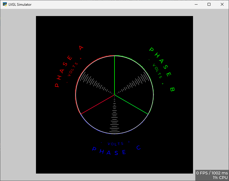
3 of them represent the voltage and they are at the fixed angles of 90, 120 and 330 as you saw on the photo and the video of the phasor diagram, the only thing that changes of these vector are the magnitude (the length of the vector), but they must be in scale.
So for example, letā€™s say the vector value to draw is from 0%, in which it is invisible, to 100% in which it basically the radius of the circle.
The maximum value (100%) depends on the scale in which the voltage value is located, the scales are 10,20,50,100,200,500,1000 Volts.

So for example if the voltage value is 450, the scale from 200 to 500 will be adopted, again, if the voltage value is 55, the scale from 50 to 100 will be adopted.
I will print these values near the graph so whoever sees it will know what the vector represents.

Second three
the other 3 represent the current, for every current vector there will be an associated angle, they start at the position of the voltage ones and they change angle and magnitude, they also have the scale like the voltage ones.

In conclusion
The graph has basically 9 paremeters:
-VoltageL1
-VoltageL2
-VoltageL3
-CurrentL1
-CurrentL2
-CurrentL3
-PhiL1
-PhiL2
-PhiL3

The first 3 parameters change only the magnitude and the scale of the first 3 vector, in which the angles are fixed.

The other 6 parameters change the magnitude, the scale and the angle of the second 3 vectors, that can move freely,

Thatā€™s all, if you have developed a simple method to draw vectors on the circle i will implement myself the scale logic, i hope this clarifies what i want to obtain (Very similar to the video on this topic linked messages above).

@kdschlosser any news?

working on it. I am trying to figure out why the damned thing isnā€™t rendering properly. I ran another piece of test code and that renders without an issue. There is something I am not seeing that is causing the issue. I am going to break the code apart into smaller pieces and test each piece. Iā€™ll find where the hangup is. I have other projects I am also working around. just have to be patient.

Thank you @kdschlosser, sorry if i disturb you. If you want, i could help with bugfixing, meanwhile, do you have a simple function to draw a line given the line size and angle? That would be great to test it on my own hardware to see if it draws well.

Thank you again.

yeah, I can do that. let me convert the circle math code to C.

ok so here you go.

This is pseudo code and I have not tested it so it may or may not function right out of the box.

I am remaping the sin and cos calls because LVGL doesnā€™t use floating point math in the typical 1.0 to -1.0 range it uses the min and max of an in16_t instead. I am sure the whole thing can be done using integer math you would be saving 4 bytes of memory by doing so. I didnā€™t feel it was worth the effort to hammer it out over 4 bytes. so I just remap the lvgl values to the normal ones used.

typedef struct {
    float x;
    float y;
} float_point_t;


float float_remap(int16_t value, int16_t old_min, int16_t old_max, float new_min, float new_max):
    return (float) (((float) (value - old_min) * (new_max - new_min)) / (float) ((old_max - old_min) + new_min));
    
    
uint16_t int_remap(float value, float old_min, float old_max, uint16_t new_min, uint16_t new_max):
    return (float) (((float) (value - old_min) * (new_max - new_min)) / (float) ((old_max - old_min) + new_min));
    

void float_point_to_lv_point(float_point_t * in_point, lv_point_t * out_point) {
    out_point->x = (lv_coord_t) in_point->x;
    out_point->y = (lv_coord_t) in_point->y;
}

void point_on_circle(int16_t degree, float_point_t * center, uint16_t radius, float_point_t * out_point){
    out_point->x = (float) center->x + ((float) radius * float_remap(lv_trigo_cos(degree), -32767, 32767, -1.0, 1.0));
    out_point->y = (float) center->y + ((float) radius * float_remap(lv_trigo_sin(degree), -32767, 32767, -1.0, 1.0));
}


// to get the engle or "degrees" from the voltage you would use the following line of code
uint16_t voltage_angle = int_remap(voltage, (float) min_voltage, (float) max_voltage, phase_start_angle, phase_stop_angle);

// to get the radius for the current you would use the following line of code.
uint16_t current_radius = int_remap(current, 0.0, (float) max_current, 0, radius_of_phasor_graph);

// now that you have those 2 you can do the calculation. the first point is known
// it is the center of the phasor graph.

// first point
float_point_t * graph_center;
graph_center->x = (float) lv_obj_get_width(graph_object) / 2.0f
graph_center->y = (float) lv_obj_get_height(graph_object) / 2.0f

float_point_t * vector_point;
// second point
point_on_circle(voltage_angle, graph_center, current_radius, vector_point);

// convert points to lv_point_t
lv_point_t point1; 
lv_point_t point2;

float_point_to_lv_point(vector_point, *point1);
float_point_to_lv_point(graph_center, *point2);

// now you have the 2 points needed to render a line on the canvas.

Thank you @kdschlosser , the first day of next week iā€™ll dig into your code and try to draw some lines on the screen.

I wanted to let you know that I have been working on this. itā€™s kind of a double project actually. I am hammering out bugs in the CPython LVGL binding I am writing at the same time. Itā€™s one of the reasons why it is taking me longer. The API is closer to C then the MicroPython binding is so it is going to be a lot easier to port over to C code.

All of that is rendered, nothing used from an image. I have to draw in the ā€œneedleā€ for each phaseā€¦

With this code you have the ability to change the size of the graph as well as any of the fonts used, all of the colors, position.

I also put into it a little bit of a bonus. It will also graph voltage drop knowing what the voltage is at a < 5 amp current draw, what the current draw is and what the voltage reading is at that time. It will graph out the the drop up to 80% of the maximum scaled ampsā€¦

@kdschlosser thank you, it seems great. :heart_eyes:

I canā€™t wait to test it on my TFT!

Feel free to email me if you need any help with something: alberto.pesce98@gmail.com

I await your news!!! Thank you again!!

I just got past a major stumbling block which was a problem in the cpython binding and allocating memory. I have not had a chance yet to see if I stop getting access violations in the code for the phasor meter. It solved the problem in other scripts so I am pretty hopeful about it solving the problem with the meter script as well. If that is fixed then finishing it up will simple be a gravy train on biscuit wheels.