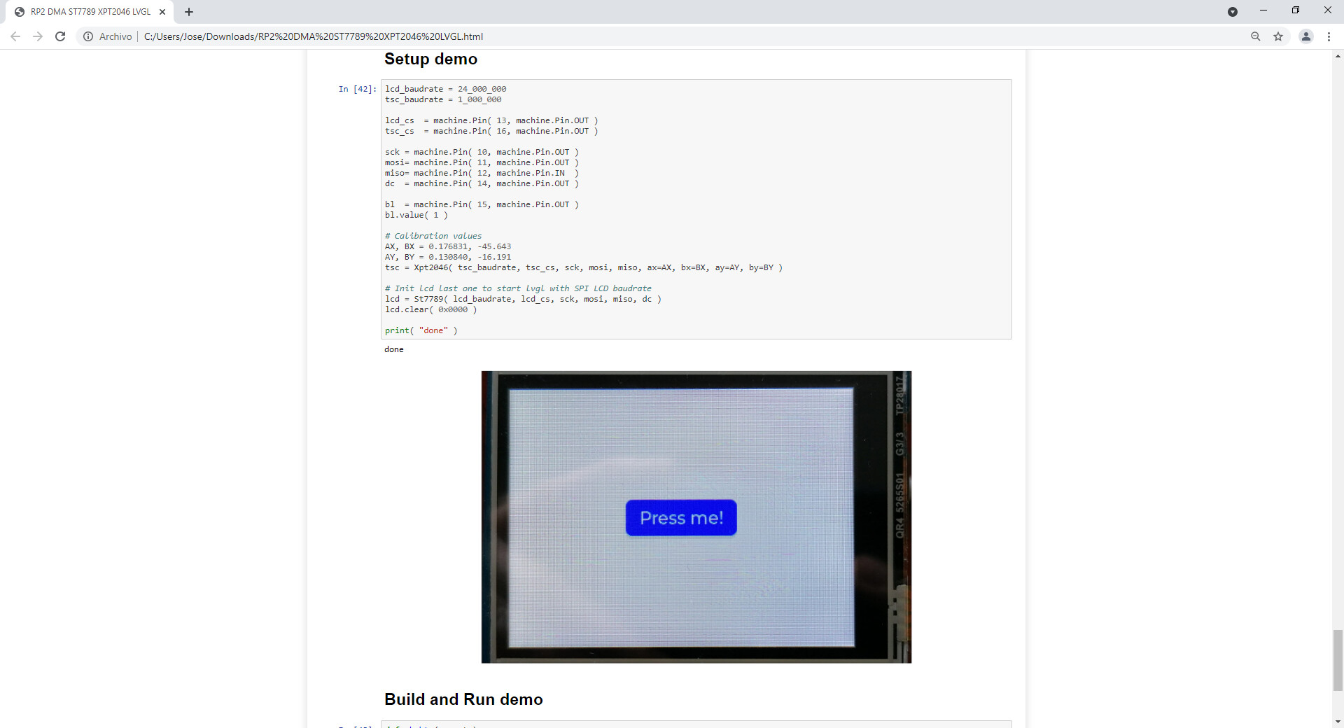
This project uses pure micropython drivers for LCD and Touch screen controller.
The LCD uses the ST7789 driver connected via SPI at 24MHz. Thanks to the DMA most work is done by hw so python implementation dosent affect to the FPS.
Where did you get the LCD/touch drivers?
If possible, it would be nice to have them as part of lv_binding_micropython repo, so they could be available for everyone.
I think the raspberry pi pico has similar power to a STM32F4 (or maybe an ESP32) … but the PIO peripheral allows it to do certain things that were previously only possible with FPGAs.
Few days ago I ran a pystone benchmark and got:
1.08[pystones/sec] on PICO @133MHz(single core)
1.04[pystones/sec] on ESP32 @240MHz
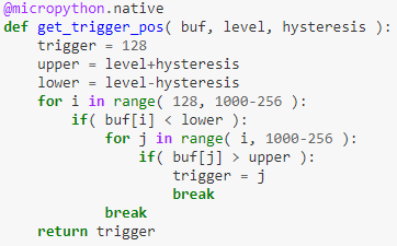
For now trigger has simplest sw implemented.
320x240. Cause is connected via SPI, I choose this “medium resolution”.
For most user interactions, where you need to refresh only small portion of the screen area, response is very fluent.
I was converting recently an application from STM32F401CE to a Pico. It does 200K ADC samples/sec with some processing at DMA interrupt level to decode and track stepper motor angle. On the STM32 the IRQ accounted to 25% of the time, on the Pico about half of that, even though there were some FP computations in the IRQ, implementing a simple signal filter.
I was very impressed. It’s also simpler, better documented, has simpler field firmware upgrade, and has a good source of high quality modules at a good price (vs the ‘blackpills’ I used) so I switched to it as my goto MCU.
Now I am trying to play with pio, to see how fast I can drive TFT updates, currently with software only its about 12M pixels/sec (16 bit data), including on the fly conversion from 8 bit color to 16 bit color.
I got an RPICO because I read about PIO and thought CM0 was a low-end CPU… but for some things I tested for weeks, it seems like it is really powerful for all tasks. I normally use CM4 / CM7 CPUs but now I’m using a CM0 and I still don’t miss anything
Sorry on the pastebin code I shared woth you, different pins where used. Check these lines:
self.db = machine.Pin( 0 ) # out
self.sck = machine.Pin( 21 ) # side 0
The PIO is configured to use 8 output pins starting at pin 0 and 1 sideset pin starting at 21
This is how micropython designed its API. Its a little bit extrage first time, but this is how it works, you only need to declare first pin and also the size of consecutive pins. I dont know where is this specified in the micropython doc, but you can check how PIO pin maps works on this video
This function declares an PIO program. This program read 8 input pins and push into the fifo.
The “.side()” code handles the sideset pin, ( that is mapped to the adc clk signal)
The DMA is also configured to read the fifo and store on the RAM.
Hello,
Can you describe a little the power scheme? I don’t really understand what do you need the second GND connected to pin 23 or 24? And also, what do you need the resistor for?
Thanks,