Hi everyone,
I’m trying to set up a board with an ESP32 and an ST7789 display.
Specifically, it’s the ESP32-2432S032 model.
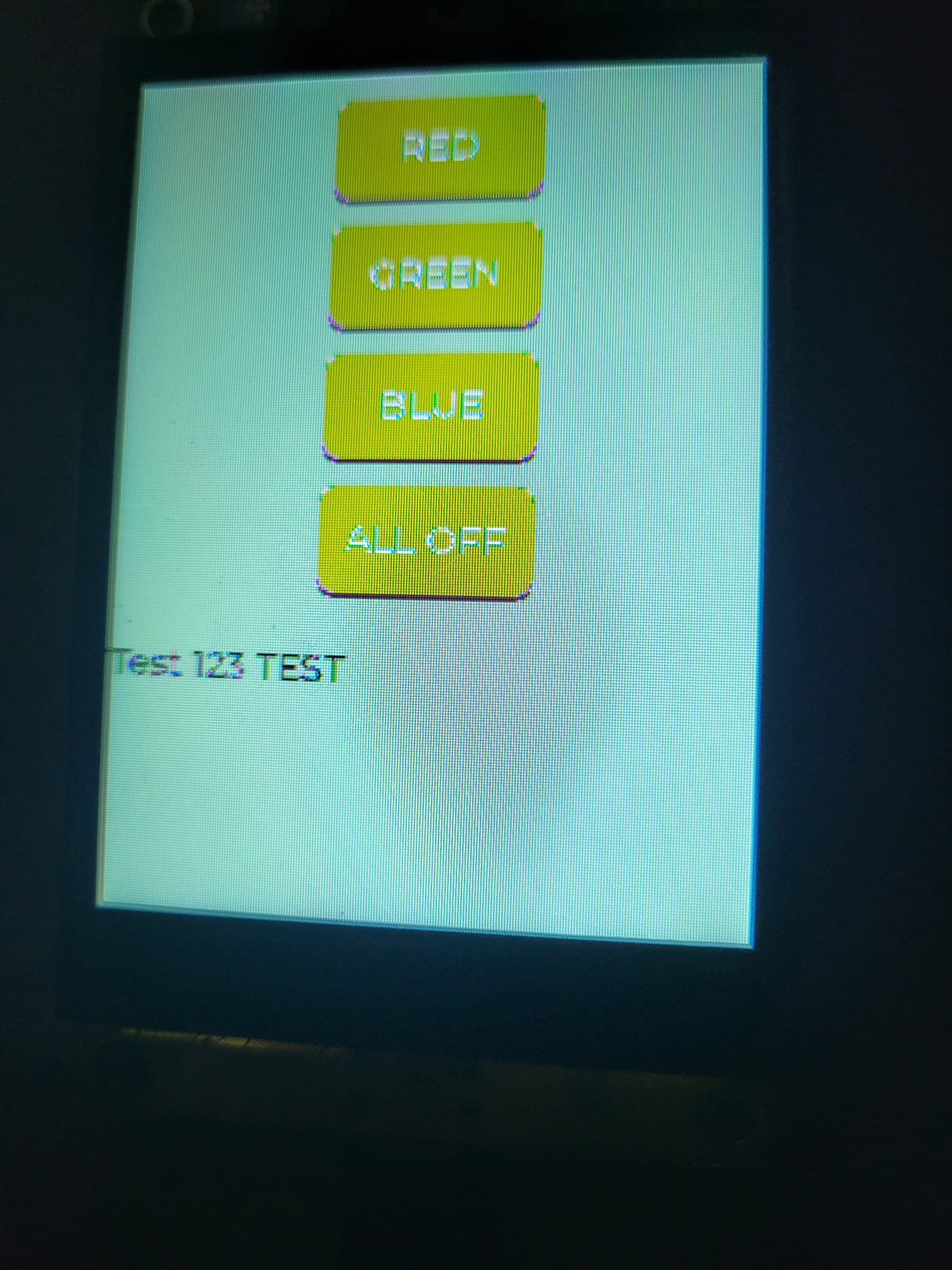
I’ve managed to get both the display and the touch working, but I can’t seem to get good image and text quality.
I’ve tried various settings, but nothing seems to help.
I’m using the ESP-IDF environment with the official Espressif drivers.
Is there anyone familiar with this board or who might have an idea of what I’m doing wrong?
With the demo that was preloaded when I received the board, even the smallest text looked great, while I can’t even get larger text to display clearly.
Everything looks very pixelated.
This is my init procedure:
#define LV_CONF_INCLUDE_SIMPLE
#include "lv_conf.h"

#include "freertos/FreeRTOS.h"
#include "freertos/task.h"
#include "driver/spi_master.h"
#include "driver/gpio.h"
#include "esp_log.h"
#include "esp_err.h"

#include "lvgl.h"
#include "esp_lvgl_port.h"
#include "esp_lcd_panel_io.h"
#include "esp_lcd_panel_interface.h"
#include "esp_lcd_panel_ops.h"
#include "esp_lcd_panel_st7789.h"

#include "driver/i2c.h"
#include "esp_lcd_touch.h"
#include "esp_lcd_touch_gt911.h"
#include "driver/ledc.h"
#include "UI.h"
#include "LED.h"
#include "Uart.h"

//Private defines -------------------------------
//ST7789/SPI
#define PIN_NOT_USED    -1
#define PIN_NUM_MOSI    GPIO_NUM_13
#define PIN_NUM_CLK     GPIO_NUM_14
#define PIN_NUM_CS      GPIO_NUM_15
#define PIN_NUM_DC      GPIO_NUM_2
#define PIN_NUM_RST     GPIO_NUM_4
#define PIN_NUM_BCKL    GPIO_NUM_27

#define LCD_H_RES       240
#define LCD_V_RES       320

//GT911/I2C
#define I2C_SDA         GPIO_NUM_33
#define I2C_SCL         GPIO_NUM_32
#define I2C_PORT        I2C_NUM_0
#define I2C_CLK_HZ      400000
#define I2C_TOUCH_NUM   0
#define GT911_INT       PIN_NOT_USED
#define GT911_RST       GPIO_NUM_25
#define GT911_ADDR      0x5D

//Private variables -----------------------------
static const char               *INIT_TAG    = "INIT";
static esp_lcd_touch_handle_t   touchHandle  = NULL;

//Private functions -----------------------------
static void touchInit   (esp_lcd_panel_io_handle_t lcdIoHandle);
static void displayInit (esp_lcd_panel_io_handle_t *lcdIoHandle, esp_lcd_panel_handle_t *lcdPanelHandle);
static void lvglInit    (esp_lcd_panel_io_handle_t io_handle, esp_lcd_panel_handle_t lcdPanelHandle);
static void st7789_send_init_cmds(esp_lcd_panel_io_handle_t io_handle);

void app_main(void)
{
    esp_lcd_panel_io_handle_t lcdIoHandle = NULL;
    esp_lcd_panel_handle_t lcdPanelHandle = NULL;

    halInit();
    uartInit();
    touchInit(lcdIoHandle);
    displayInit(&lcdIoHandle, &lcdPanelHandle);
    lvglInit(lcdIoHandle, lcdPanelHandle);

    createUI();

    char s[] = "Uart test\r\n";
    uartWriteData(s, sizeof(s));

    //Attivo il task per la ricezione di dati in seriale
    xTaskCreate(uartEventTask, "uartEventTask", 4096, NULL, 10, NULL);
}


static void touchInit(esp_lcd_panel_io_handle_t lcdIoHandle)
{
    const esp_lcd_panel_io_i2c_config_t lcdIoI2cConfig = ESP_LCD_TOUCH_IO_I2C_GT911_CONFIG();

    //I2C
    const i2c_config_t i2cConf =
    {
        .mode = I2C_MODE_MASTER,
        .sda_io_num = I2C_SDA,
        .scl_io_num = I2C_SCL,
        .sda_pullup_en = GPIO_PULLUP_DISABLE,
        .scl_pullup_en = GPIO_PULLUP_DISABLE,
        .master.clk_speed = I2C_CLK_HZ
    };

    //Touch HW
    const esp_lcd_touch_config_t lcdTouchCfg =
    {
        .x_max = LCD_H_RES,
        .y_max = LCD_V_RES,
        .rst_gpio_num = GT911_RST,
        .int_gpio_num = GT911_INT,
        .levels =
        {
            .reset = 0,
            .interrupt = 0,
        },
        .flags =
        {
            .swap_xy = 0,
            .mirror_x = 1,
            .mirror_y = 0,
        },
    };

    ESP_LOGI(INIT_TAG, "Init i2c...");
    ESP_ERROR_CHECK(i2c_param_config(I2C_TOUCH_NUM, &i2cConf));
    ESP_ERROR_CHECK(i2c_driver_install(I2C_TOUCH_NUM, i2cConf.mode, 0, 0, 0));

    ESP_LOGI(INIT_TAG, "Create touch device...");
    ESP_ERROR_CHECK(esp_lcd_new_panel_io_i2c((esp_lcd_i2c_bus_handle_t)I2C_TOUCH_NUM, &lcdIoI2cConfig, &lcdIoHandle));
    ESP_ERROR_CHECK(esp_lcd_touch_new_i2c_gt911(lcdIoHandle, &lcdTouchCfg, &touchHandle));
}


static void displayInit(esp_lcd_panel_io_handle_t *lcdIoHandle, esp_lcd_panel_handle_t *lcdPanelHandle)
{
    spi_bus_config_t busCfg =
    {
        .mosi_io_num = PIN_NUM_MOSI,
        .miso_io_num = PIN_NOT_USED,
        .sclk_io_num = PIN_NUM_CLK,
        .quadwp_io_num = PIN_NOT_USED,
        .quadhd_io_num = PIN_NOT_USED,
        .max_transfer_sz = LCD_H_RES * 40 * sizeof(uint16_t),
    };

    esp_lcd_panel_io_spi_config_t ioCfg =
    {
        .dc_gpio_num = PIN_NUM_DC,
        .cs_gpio_num = PIN_NUM_CS,
        .pclk_hz = 20 * 1000 * 1000,
        .spi_mode = 0,
        .trans_queue_depth = 10,
        .lcd_cmd_bits = 8,
        .lcd_param_bits = 8,
        .on_color_trans_done = NULL,
        .user_ctx = NULL,
    };

    esp_lcd_panel_dev_config_t panelCfg =
    {
        .reset_gpio_num = PIN_NUM_RST,
        .color_space = ESP_LCD_COLOR_SPACE_RGB,
        .bits_per_pixel = 16,
    };

    ESP_LOGI(INIT_TAG, "Init SPI master...");
    ESP_ERROR_CHECK(spi_bus_initialize(SPI2_HOST, &busCfg, SPI_DMA_CH_AUTO));

    ESP_LOGI(INIT_TAG, "Create SPI interface...");
    ESP_ERROR_CHECK(esp_lcd_new_panel_io_spi(SPI2_HOST, &ioCfg, lcdIoHandle));

    ESP_LOGI(INIT_TAG, "Create ST7789...");
    ESP_ERROR_CHECK(esp_lcd_new_panel_st7789(*lcdIoHandle, &panelCfg, lcdPanelHandle));

    ESP_ERROR_CHECK(esp_lcd_panel_reset(*lcdPanelHandle));
    ESP_ERROR_CHECK(esp_lcd_panel_init(*lcdPanelHandle));
    ESP_ERROR_CHECK(esp_lcd_panel_invert_color(*lcdPanelHandle, true));
    ESP_ERROR_CHECK(esp_lcd_panel_disp_on_off(*lcdPanelHandle, true));


    ESP_LOGI(INIT_TAG, "Backlight ON...");
    gpio_config_t backlightCfg =
    {
        .mode = GPIO_MODE_OUTPUT,
        .pin_bit_mask = 1ULL << PIN_NUM_BCKL,
    };

    gpio_config(&backlightCfg);
    gpio_set_level(PIN_NUM_BCKL, 1);
}


static void lvglInit(esp_lcd_panel_io_handle_t lcdIoHandle, esp_lcd_panel_handle_t lcdPanelHandle)
{
    lvgl_port_cfg_t lvglPortCfg =
    {
        .task_priority = 2,
        .task_stack = 8192,
        .task_affinity = 0,
        .task_max_sleep_ms = 10,
        .timer_period_ms = 5,
    };

    lvgl_port_display_cfg_t lvglCfg =
    {
        .io_handle = lcdIoHandle,
        .panel_handle = lcdPanelHandle,
        .buffer_size = LCD_H_RES * 20,
        .double_buffer = true,
        .hres = LCD_H_RES,
        .vres = LCD_V_RES,
        .color_format = LV_COLOR_FORMAT_RGB565,
        .monochrome = false,
    };

    lvgl_port_touch_cfg_t touchCfg =
    {
        .handle = touchHandle,
    };

    ESP_LOGI(INIT_TAG, "Init LVGL...");
    ESP_ERROR_CHECK(lvgl_port_init(&lvglPortCfg));

    ESP_LOGI(INIT_TAG, "Add LCD panel to LVGL...");
    lv_display_t *disp = lvgl_port_add_disp(&lvglCfg);
    assert(disp != NULL);

    ESP_LOGI(INIT_TAG, "Add touch panel to LVGL...");
    touchCfg.disp = disp;
    lv_indev_t *indev = lvgl_port_add_touch(&touchCfg);
    if (!indev)
    {
        ESP_LOGE("LVGL", "Touch panel init error!");
        abort();
    }

    lv_disp_set_rotation(disp, LV_DISPLAY_ROTATION_0);


    st7789_send_init_cmds(lcdIoHandle);
}


esp_err_t err;
esp_lcd_panel_io_handle_t panel_io;

#define ST7789_CMD_COLMOD  0x3A
#define ST7789_CMD_MADCTL  0x36
#define ST7789_CMD_SLPOUT  0x11
#define ST7789_CMD_DISPON  0x29
#define ST7789_CMD_NORON   0x13

#define LCD_DELAY(ms) vTaskDelay(pdMS_TO_TICKS(ms))

void st7789_send_init_cmds(esp_lcd_panel_io_handle_t panel_io)
{
    esp_err_t err = ESP_OK;
    uint8_t data;

    // SLPOUT
    err |= esp_lcd_panel_io_tx_param(panel_io, 0x11, NULL, 0);
    vTaskDelay(pdMS_TO_TICKS(120));

    // COLMOD = 0x55 (16bit color - RGB565)
    data = 0x55;
    err |= esp_lcd_panel_io_tx_param(panel_io, 0x3A, &data, 1);

    // MADCTL = 0x00 (no rotation, RGB order)
    data = 0x00;
    err |= esp_lcd_panel_io_tx_param(panel_io, 0x36, &data, 1);

    // B2 - Porch control
    uint8_t b2_data[5] = { 0x0C, 0x0C, 0x00, 0x33, 0x33 };
    err |= esp_lcd_panel_io_tx_param(panel_io, 0xB2, b2_data, sizeof(b2_data));

    // Power control sequence
    uint8_t cmds[][2] = {
        { 0xB7, 0x35 },
        { 0xBB, 0x19 },
        { 0xC0, 0x2C },
        { 0xC2, 0x01 },
        { 0xC3, 0x12 },
        { 0xC4, 0x20 },
        { 0xC6, 0x0F },
    };
    for (int i = 0; i < sizeof(cmds)/2; i++) {
        err |= esp_lcd_panel_io_tx_param(panel_io, cmds[i][0], &cmds[i][1], 1);
    }

    // D0 - Power control with 2 bytes
    uint8_t d0_data[2] = { 0xA4, 0xA1 };
    err |= esp_lcd_panel_io_tx_param(panel_io, 0xD0, d0_data, sizeof(d0_data));

    // Gamma correction
    uint8_t gamma_pos[14] = {
        0xF0, 0x09, 0x13, 0x12, 0x12, 0x2B, 0x3C,
        0x44, 0x4B, 0x1B, 0x18, 0x17, 0x1D, 0x21
    };
    err |= esp_lcd_panel_io_tx_param(panel_io, 0xE0, gamma_pos, sizeof(gamma_pos));

    uint8_t gamma_neg[14] = {
        0xF0, 0x09, 0x13, 0x0C, 0x0D, 0x27, 0x3B,
        0x44, 0x4D, 0x0B, 0x17, 0x17, 0x1D, 0x21
    };
    err |= esp_lcd_panel_io_tx_param(panel_io, 0xE1, gamma_neg, sizeof(gamma_neg));

    // NORON
    err |= esp_lcd_panel_io_tx_param(panel_io, 0x13, NULL, 0);
    vTaskDelay(pdMS_TO_TICKS(10));

    // DISPON
    err |= esp_lcd_panel_io_tx_param(panel_io, 0x29, NULL, 0);

    if (err != ESP_OK) {
        ESP_LOGE("ST7789", "Error during display init: %s", esp_err_to_name(err));
    } else {
        ESP_LOGI("ST7789", "Display init success");
    }
}
The st7789_send_init_cmds function was added later on to see if I could improve the situation.
Thanks to anyone willing to help!