Using Normal Maps and Additive / Multiply Blending to simulate metallic shininess

The simulator runs on the client side. It is running locally when using it. The problem is it uses javascript which adds a lot of additional overhead. There are also had set time limits to how fast things can run. They can be overridden and you would need to add additional code to do that. It’s more complicated is all.

If you get WSL and Ubuntu up and running I can send you the binary for micropython and it is far easier to override refresh timers because of how I wrote it. There are going to be some requirements you will need to get installed into Ubuntu which is easily done. It’s also a single file binary so not complicated to run it.

I believe I can also clean up the output image. I am going to work on that now.

Great, it’s my day off here from work so I’ll try to get that setup today. If not today, then two days forward. I work long shifts every other day and it’s very physically demanding, so I need a while to recharge after.

BTW regarding the noise you may have noticed in the output image, some of that I believe is a result of the dithering I allowed the image converter to do. Here is the image as raw PNG in case you want to try other conversions. I think turning off dithering would help for sharper lines, but would look more pixelated too.

sphere_uv

Here’s the Blender scene for version 4.2.0, should open fine in newer too, I think I’m a couple minor updates behind current.

Sphere UVtex scene blender420.zip (470.0 KB)

Here is the output image…

You can see it is not very clean. The translation calculation is off somewhere.

you are using the colors in the colored sphere to decide what pixel gets collected from the source image correct?

That’s right, the UVTex sphere channels are just the U/V texture co-ordinates of a given shape at a certain point on the screen. Those specify which portion of the source texture to put at that pixel. Normally they’re expressed in the 0->1 range, but here we just leave it as a byte and work with it from there. So far all my source images have been some unit of 64 so it’s easy enough to bit shift those byte values around and avoid the floats.

I’ll make another version here without the dithering and I think that’ll remove the fuzz you’re seeing. Avoid lossy compressing these images, it will mess them up badly.

I guess what I am confused by is this…

In your color map the red and green pixels are what change value. I am guessing that red represents the X axis and green represents the Y axis. At least that is kind of the way it appears to be. The green is flipped so the colors runs from max to min as the Y axis increases.

It also looks like the colors are mapped so it is supposed to give the coordinates for 256 x 256 sized image and not a 256, 128 sized image

Looking at your code you are collecting the x and y coordinates as follows.

moving_rX = (rPix[rIndex + 2] + oX) % 256  # capturing blue?
moving_rY = (256 - rPix[rIndex + 1] + oY) % 128  # capturing green?

rIndex is the start of a pixel and pixels are stored as r, g, b, a. so rIndex + 2 would be the index for the blue pixel. The blue flips between 1 and 0 so I am not 100% sure what it is supposed to represent.

Yeah that’s weird, right? I can’t explain that, for whatever reason it seems to be stored as BGRA, because when I use rPix[rIndex + 0] for moving_rX, I get nothing.

About the 256 value range for a max 128 value image… I’m encoding the maximum range into the UVTex, and then pruning it down as needed for the application at hand, in this case as you said, 256x128. I think I’m actually mangling the Y co-ord with that “% 128”, causing it to loop instead of scale, and that’s the part that looks broken to you. Good catch, it is broken. But in this specific use case, it’s hard to notice and it helps stretch out the texture in a way that feels more spatially accurate to me. I think I originally bitshifted green right one bit to put it in the right range, and for whatever reason I liked the look of this now better.

hold on a second I am going to use the texture data to create a PNG image to see if the colors come out the same as what you attached a couple of posts back…

OK I just made another version without dithering on in the image converter and it’s exactly the same so I guess I never had dithering on to begin with, it’s some other issue. What I’ll try here is outputting the image from blender with 16 bit color channels, instead of 8 bit standard, and then reducing that to 8 bit some other way. I suspect Blender is the culprit here, but to it’s credit in most situations this noising effect would actually help overall image quality. But not in this edge case.

edit: Future me, here it is
sphere_uv_hiqual

image

that’s your texture map.

Using 16 bit channels (and a much higher sample count in Blender while rendering) have fixed the noising issue:

image

here is the latest version, swap out make_sample_img2() with this version and it should clean it up for you there.

simulator_refmap_test2c_micropython.zip (77.7 KB)

Hey lurkers! Is anyone looking for a way to get involved and not sure where they fit in? Here’s what I’d like to do, maybe you can help: With this sphere example, I think what would look really cool is a way for users to draw points, paths or random scribbles onto the sphere, to demonstrate that it can be fully dynamic. Perhaps this could be used to visualize air flight paths, or some sort of ‘WarGames’-esque display.

Basically all we’d need is a dynamic, user generated 256x128 overlay image that gets combined with the worldmap, prior to reprojection. So if you make a way to add points and graphics into an empty image of that size, merging it in with the worldmap should be pretty straightforward.

Eventually I’ll do something to that effect if no one else does, but feel free to take a shot at it and post what you come up with, I’m sure it will help.

What I am trying to think of is an easy way for a user to be able to make the texture map because it could apply to all kinds of shapes and not just spheres. Blender is an exceedingly complicated program to use especially for someone that hasn’t used it at all. I have done basic things in blender but making a texture map using it is above what I am able to do.

The texture map we could make 1/2 the size because the blue and alpha channels are not used. 0, 0 could be used to skip meaning not to map anything and it would be a simple task of reducing the values by 1 if it is not 0, 0 to get the actual correct mapped coordinates. While I do understand that using a texture map that is standardized would be the ideal thing to do the problem ends up being memory use and storage. MCU’s are very tight on resources.

So here’s another interesting render of the sphere.
sphere_normal
Instead of the UV texture cordinates, this is showing the vector normals (as the original monkey sample did). This image does not work for texture remapping, however it works great for applying a metallic refmap. I’m torn between trying to encode the r/g (b discarded, it’s implied) into the one unused channel, and simply storing it as it’s own image. Probably just as well to have it separate. Once frame rate is doing well enough in it’s current state, my plan is to actually use the same idea in two phases, one for texture, the other for lighting / material. So we could have the spinning globe made of spatially lit shiny gold etc.

Another thing I might try in the future is providing the refmap at several levels of blur, then using an unused color channel in the source image to specify which of those blur-levels to sample the refmap from at a given pixel. That will create the effect of multiple shiny/flat surfaces and levels in between (one per blur state). The blur states could be different hue’s, even, and in that case it’s more like each blur state is it’s own specific material.

it’s very possible to dynamically generate these source images, I’m sure. Maybe not for 3d monkey’s, but definitely for stuff like spheres and planes. Probably wouldn’t take long at boot to compute it, and that would offer best quality too. For a plane, for example, we’d just need to construct a 3d quad out of 4 points in a square, then project those points in some simplified 3d spatial model onto a 2d plane (the camera), and from those 4 now 2d points (all of which are likely outside of the actual edges of the screen btw), draw a dual horizontal/vertical gradient.

Consider reading up on 3d graphics and UV texture mapping for more information on this. Simplified versions are realistic for us to implement I think.

You may find the vertex shader portion of a basic ‘hello world’ realtime shader example informative, it will likely discuss how points go from x/y/z/u/v into screen space 2d coordinates and how those now 2d triangles are then rasterized into a grid of pixels (in the fragment shader portion). Godot is a good, open source way to experiment with custom shaders yourself and get immediate previews.

A little bit of matrix math would go a long way towards this btw. I looked around to see what kind of micropython options exist to this end, without going full-numpy, something much more minimal would be appropriate I think. I didn’t find much so I copy/pasted a few things together from some stackexchange posts, and actually have a version that does much of the above already (without actually rendering anything, I was just using it to try to rotate the source normal instead of shifting it, but that’s not really working out right yet). Using completely homespun matrix math will also be easier to port to C, but I’m sure viper could do it too.

These integer UV values can actually be interpolated pretty well too, so if our UVTex is at 128x128, but the retex is 512x64, if you take the 4 pixels a floating point pixel position would partially sit within and blend those together, the resulting UV co-ord will be pretty close to what it would have been if the UVtex had been rendered at a much higher resolution. Maybe the overhead could be reduced somewhat with this, but it would involve more realtime CPU usage. In the event that one output pixel represents multiple input pixels (like the 64 height of above example), multiple source pixels could be sampled and blended to create a blended effect. In realtime 3d, this source/output pixel density ratio is used to determine which mipmap level to sample from, where each mipmap is the source texture downsampled by a power of two until it’s only one pixel tall. That’s how distant textures don’t look so noisy in modern graphics, and is the most performant current system for visualizing multiple source pixels within one output pixel.

I’ll follow this as a model for future tests. I suspect we’ll be able to shave a few clock samples off further by doing things like recycling the buffer index calculation, and just incrementing it by a set amount per pixel instead. There’s big advantages to using image sizes that allow any multiplications or divisions in those calculations to be (mostly) bitshifts.

One of the things you are also forgetting is that you can also increase the the precision of the texture map by using the odd/even of the x, y coordinates. as an example. If you have a texture map that is 64 x 64 and you want to map that to a 128 x 128 image the values that are stored in the texture map can be adjusted an amount based on the parity of the x, y coordinates. you can adjust the stored value if x and or y is even or odd. It’s simple addition or subtraction or maybe bit shifting the stored values so the cost would be minimal to execute.

In a static design where the texture map is only applied a single time to an image the texture map could be loaded like a file where only the bytes that are needed would take up memory instead of having an array with the entire texture. If the texture is applied to an image dynamically like what is happening in your globe example then you would want the texture loaded into an array.

Hi just wanted to update on something I’m working on here. As kdschlosser mentioned, resources on MC’s are very sparse so the less RAM we can use with this the better. To that end, I’m working on a way to store the UVTex (or NormalTex) images at extremely low resolution, and then interpolate the sparse data up to the required resolution at runtime (without baking that scaled image into a new larger image which would itself use up the RAM we’re trying to save).

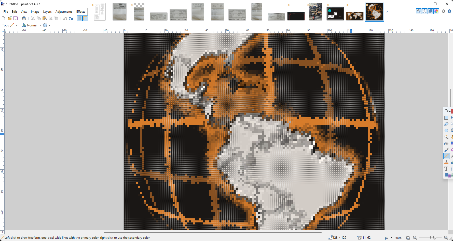
Results are very promising so far. I have made a version of the UVTex above that’s normally at 128x128x4, and instead it’s at 32x32x4 and will soon be 32x32x2. It seems that interpolating the ‘in-between’ pixels produces results that are accurate enough to be acceptable, with some dodgey bits around the edges I’m still working on. So the image quality is good enough, unfortunately the runtime speed took an absolute nose-dive trying it this way, and I’m still struggling with more ways to optimize it back into the acceptable range. The main problem is that to do this interpolation, I have to sample 4 source pixels per output pixel, and that gets expensive.

One strategy I’m trying now is recycling 2 of those lookups per cycle, so the new Upper-Left and Lower-Left pixels are just the last cycles Upper-Right and Lower-Right pixels. Maybe I can have that ready to demo soon and hopefully that will help shave some clock cycles off the process

If anyone has any suggestions for the most performant way to sample, for example, a 32x32 bitmap at 128x128 resolution without using 128x128x4 ram to store a buffered copy of the rescaled tiny version, let’s hear it I’m all ears.

If this approach can be made fast enough, we could concievably store these lookup textures at rediculously low resolution, and then mask them out with much more compact 1/2/4 bit alpha images so for example the edges of the circle can be nice and sharp.

Gotta work tho so I’ll be out a while, will update tomorrow sometime with screenshots and samples.

EDIT: I see the forum software is advising people not to reply further because this problem has been solved. I think in this case, this problem could never be solved enough, so if anyone has further thoughts please feel free to provide them, even if it’s years later.

get rid of the multi step rendering and render the entire thing in a single go. It will be a lot easier to do the recycling you want if you do that. You don’t need to use the multiple calls to update in order to reduce anomalies that were happening. Because of using the double buffer those anomalies will not occur and it would be far more efficient to just do the iteration a single time over all of the pixels and remove the math used to compute the y axis.