Description
What MCU/Processor/Board and compiler are you using?
STM32 NUCLEO-F756ZG, STM32CubeIDE, 2.8 inch Resistive touch LCD ( Pico-ResTouch-LCD-2.8 - Waveshare Wiki)
What LVGL version are you using?
Latest
What do you want to achieve?
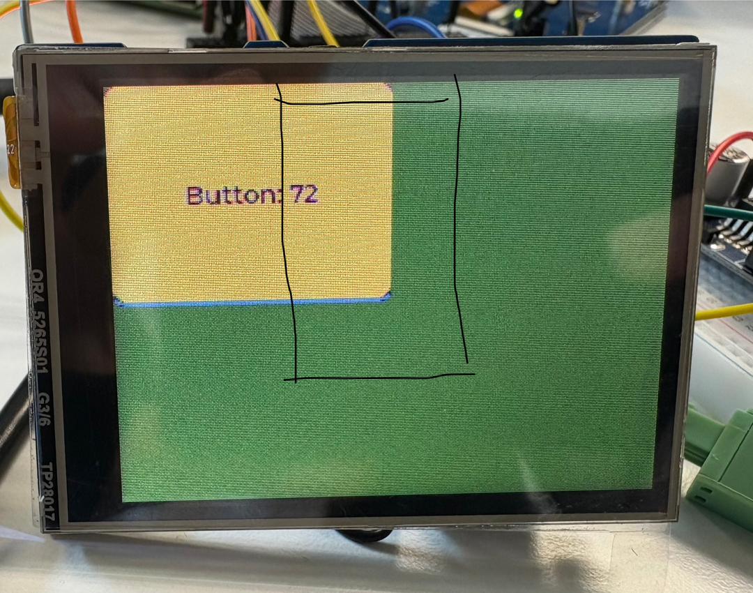
Touch area fitting the buttons position.
Code to reproduce
/* Includes ------------------------------------------------------------------*/
#include "main.h"
#include "cmsis_os.h"

/* Private includes ----------------------------------------------------------*/
/* USER CODE BEGIN Includes */
#include "lvgl.h"
#include "./src/drivers/display/st7789/lv_st7789.h"
#include <stdbool.h>
/* USER CODE END Includes */

/* Private typedef -----------------------------------------------------------*/
/* USER CODE BEGIN PTD */

/* USER CODE END PTD */

/* Private define ------------------------------------------------------------*/
/* USER CODE BEGIN PD */
#define LCD_H_RES       240
#define LCD_V_RES       320
#define BUS_SPI1_POLL_TIMEOUT 0x1000U

#define XPT2046_CS_LOW()   HAL_GPIO_WritePin(TP_CS_GPIO_Port, TP_CS_Pin, GPIO_PIN_RESET)
#define XPT2046_CS_HIGH()  HAL_GPIO_WritePin(TP_CS_GPIO_Port, TP_CS_Pin, GPIO_PIN_SET)
/* USER CODE END PD */

/* Private macro -------------------------------------------------------------*/
/* USER CODE BEGIN PM */

/* USER CODE END PM */

/* Private variables ---------------------------------------------------------*/

SPI_HandleTypeDef hspi1;
SPI_HandleTypeDef hspi2;
DMA_HandleTypeDef hdma_spi1_tx;
DMA_HandleTypeDef hdma_spi2_tx;

UART_HandleTypeDef huart6;

osThreadId defaultTaskHandle;
/* USER CODE BEGIN PV */
osThreadId LvglTaskHandle;
lv_display_t *lcd_disp;
volatile int lcd_bus_busy = 0;
lv_indev_t * indev;

uint8_t tx_buffer1[50] = "Detected!\n\r";
uint8_t tx_buffer2[50] = "None\n\r";
/* USER CODE END PV */

/* Private function prototypes -----------------------------------------------*/
void SystemClock_Config(void);
static void MX_GPIO_Init(void);
static void MX_DMA_Init(void);
static void MX_SPI1_Init(void);
static void MX_SPI2_Init(void);
static void MX_USART6_UART_Init(void);
void StartDefaultTask(void const * argument);

/* USER CODE BEGIN PFP */
void ui_init(lv_display_t *disp);
void LVGL_Task(void const *argument);
/* USER CODE END PFP */

/* Private user code ---------------------------------------------------------*/
/* USER CODE BEGIN 0 */
static uint16_t xpt2046_read(uint8_t command) {
	uint8_t tx[3] = {command, 0x00, 0x00};
	uint8_t rx[3];

	hspi1.Init.DataSize = SPI_DATASIZE_8BIT;
	HAL_SPI_Init(&hspi1);

	XPT2046_CS_LOW();
	HAL_SPI_TransmitReceive(&hspi1, tx, rx, 3, HAL_MAX_DELAY);
	XPT2046_CS_HIGH();

	return((rx[1] << 8) | rx[2]) >> 3;
}

static bool touchpad_is_pressed(int32_t * x, int32_t * y) {
	const uint8_t CMD_X = 0x90;
	const uint8_t CMD_Y = 0xD0;

	uint16_t raw_y = xpt2046_read(CMD_Y);
	uint16_t raw_x = xpt2046_read(CMD_X);

	snprintf(tx_buffer1, sizeof(tx_buffer1), "X:%u Y:%u\r\n", *x, *y);
	HAL_UART_Transmit(&huart6, (uint8_t*)tx_buffer1, strlen(tx_buffer1), HAL_MAX_DELAY);

	if (raw_x > 100 && raw_x < 4000 && raw_y < 4000)
		{

			*x = (raw_x - 511) * LCD_V_RES  / (3968 - 511);
			*y = LCD_H_RES - ((raw_y - 511) * LCD_H_RES / (3712 - 511));

			return true;
		}

		return false;
}
/* USER CODE END 0 */

/**
  * @brief  The application entry point.
  * @retval int
  */
int main(void)
{

  /* USER CODE BEGIN 1 */

  /* USER CODE END 1 */

  /* MCU Configuration--------------------------------------------------------*/

  /* Reset of all peripherals, Initializes the Flash interface and the Systick. */
  HAL_Init();

  /* USER CODE BEGIN Init */

  /* USER CODE END Init */

  /* Configure the system clock */
  SystemClock_Config();

  /* USER CODE BEGIN SysInit */

  /* USER CODE END SysInit */

  /* Initialize all configured peripherals */
  MX_GPIO_Init();
  MX_DMA_Init();
  MX_SPI1_Init();
  MX_SPI2_Init();
  MX_USART6_UART_Init();
  /* USER CODE BEGIN 2 */

  /* USER CODE END 2 */

  /* USER CODE BEGIN RTOS_MUTEX */
  /* add mutexes, ... */
  /* USER CODE END RTOS_MUTEX */

  /* USER CODE BEGIN RTOS_SEMAPHORES */
  /* add semaphores, ... */
  /* USER CODE END RTOS_SEMAPHORES */

  /* USER CODE BEGIN RTOS_TIMERS */
  /* start timers, add new ones, ... */
  /* USER CODE END RTOS_TIMERS */

  /* USER CODE BEGIN RTOS_QUEUES */
  /* add queues, ... */
  /* USER CODE END RTOS_QUEUES */

  /* Create the thread(s) */
  /* definition and creation of defaultTask */
  osThreadDef(defaultTask, StartDefaultTask, osPriorityNormal, 0, 128);
  defaultTaskHandle = osThreadCreate(osThread(defaultTask), NULL);

  /* USER CODE BEGIN RTOS_THREADS */
  /* add threads, ... */
  osThreadDef(LvglTask, LVGL_Task, osPriorityIdle, 0, 1024);
  LvglTaskHandle = osThreadCreate(osThread(LvglTask), NULL);

  /* USER CODE END RTOS_THREADS */

  /* Start scheduler */
  osKernelStart();

  /* We should never get here as control is now taken by the scheduler */

  /* Infinite loop */
  /* USER CODE BEGIN WHILE */
  while (1)
  {
    /* USER CODE END WHILE */

    /* USER CODE BEGIN 3 */
  }
  /* USER CODE END 3 */
}

/**
  * @brief System Clock Configuration
  * @retval None
  */
void SystemClock_Config(void)
{
  RCC_OscInitTypeDef RCC_OscInitStruct = {0};
  RCC_ClkInitTypeDef RCC_ClkInitStruct = {0};

  /** Configure LSE Drive Capability
  */
  HAL_PWR_EnableBkUpAccess();

  /** Configure the main internal regulator output voltage
  */
  __HAL_RCC_PWR_CLK_ENABLE();
  __HAL_PWR_VOLTAGESCALING_CONFIG(PWR_REGULATOR_VOLTAGE_SCALE1);

  /** Initializes the RCC Oscillators according to the specified parameters
  * in the RCC_OscInitTypeDef structure.
  */
  RCC_OscInitStruct.OscillatorType = RCC_OSCILLATORTYPE_HSE;
  RCC_OscInitStruct.HSEState = RCC_HSE_BYPASS;
  RCC_OscInitStruct.PLL.PLLState = RCC_PLL_ON;
  RCC_OscInitStruct.PLL.PLLSource = RCC_PLLSOURCE_HSE;
  RCC_OscInitStruct.PLL.PLLM = 4;
  RCC_OscInitStruct.PLL.PLLN = 216;
  RCC_OscInitStruct.PLL.PLLP = RCC_PLLP_DIV2;
  RCC_OscInitStruct.PLL.PLLQ = 3;
  if (HAL_RCC_OscConfig(&RCC_OscInitStruct) != HAL_OK)
  {
    Error_Handler();
  }

  /** Activate the Over-Drive mode
  */
  if (HAL_PWREx_EnableOverDrive() != HAL_OK)
  {
    Error_Handler();
  }

  /** Initializes the CPU, AHB and APB buses clocks
  */
  RCC_ClkInitStruct.ClockType = RCC_CLOCKTYPE_HCLK|RCC_CLOCKTYPE_SYSCLK
                              |RCC_CLOCKTYPE_PCLK1|RCC_CLOCKTYPE_PCLK2;
  RCC_ClkInitStruct.SYSCLKSource = RCC_SYSCLKSOURCE_PLLCLK;
  RCC_ClkInitStruct.AHBCLKDivider = RCC_SYSCLK_DIV1;
  RCC_ClkInitStruct.APB1CLKDivider = RCC_HCLK_DIV4;
  RCC_ClkInitStruct.APB2CLKDivider = RCC_HCLK_DIV2;

  if (HAL_RCC_ClockConfig(&RCC_ClkInitStruct, FLASH_LATENCY_7) != HAL_OK)
  {
    Error_Handler();
  }
}

/**
  * @brief SPI1 Initialization Function
  * @param None
  * @retval None
  */
static void MX_SPI1_Init(void)
{

  /* USER CODE BEGIN SPI1_Init 0 */

  /* USER CODE END SPI1_Init 0 */

  /* USER CODE BEGIN SPI1_Init 1 */

  /* USER CODE END SPI1_Init 1 */
  /* SPI1 parameter configuration*/
  hspi1.Instance = SPI1;
  hspi1.Init.Mode = SPI_MODE_MASTER;
  hspi1.Init.Direction = SPI_DIRECTION_2LINES;
  hspi1.Init.DataSize = SPI_DATASIZE_8BIT;
  hspi1.Init.CLKPolarity = SPI_POLARITY_LOW;
  hspi1.Init.CLKPhase = SPI_PHASE_1EDGE;
  hspi1.Init.NSS = SPI_NSS_SOFT;
  hspi1.Init.BaudRatePrescaler = SPI_BAUDRATEPRESCALER_8;
  hspi1.Init.FirstBit = SPI_FIRSTBIT_MSB;
  hspi1.Init.TIMode = SPI_TIMODE_DISABLE;
  hspi1.Init.CRCCalculation = SPI_CRCCALCULATION_DISABLE;
  hspi1.Init.CRCPolynomial = 7;
  hspi1.Init.CRCLength = SPI_CRC_LENGTH_DATASIZE;
  hspi1.Init.NSSPMode = SPI_NSS_PULSE_DISABLE;
  if (HAL_SPI_Init(&hspi1) != HAL_OK)
  {
    Error_Handler();
  }
  /* USER CODE BEGIN SPI1_Init 2 */

  /* USER CODE END SPI1_Init 2 */

}

/**
  * @brief SPI2 Initialization Function
  * @param None
  * @retval None
  */
static void MX_SPI2_Init(void)
{

  /* USER CODE BEGIN SPI2_Init 0 */

  /* USER CODE END SPI2_Init 0 */

  /* USER CODE BEGIN SPI2_Init 1 */

  /* USER CODE END SPI2_Init 1 */
  /* SPI2 parameter configuration*/
  hspi2.Instance = SPI2;
  hspi2.Init.Mode = SPI_MODE_MASTER;
  hspi2.Init.Direction = SPI_DIRECTION_2LINES;
  hspi2.Init.DataSize = SPI_DATASIZE_8BIT;
  hspi2.Init.CLKPolarity = SPI_POLARITY_LOW;
  hspi2.Init.CLKPhase = SPI_PHASE_1EDGE;
  hspi2.Init.NSS = SPI_NSS_SOFT;
  hspi2.Init.BaudRatePrescaler = SPI_BAUDRATEPRESCALER_2;
  hspi2.Init.FirstBit = SPI_FIRSTBIT_MSB;
  hspi2.Init.TIMode = SPI_TIMODE_DISABLE;
  hspi2.Init.CRCCalculation = SPI_CRCCALCULATION_DISABLE;
  hspi2.Init.CRCPolynomial = 7;
  hspi2.Init.CRCLength = SPI_CRC_LENGTH_DATASIZE;
  hspi2.Init.NSSPMode = SPI_NSS_PULSE_DISABLE;
  if (HAL_SPI_Init(&hspi2) != HAL_OK)
  {
    Error_Handler();
  }
  /* USER CODE BEGIN SPI2_Init 2 */

  /* USER CODE END SPI2_Init 2 */

}

/**
  * @brief USART6 Initialization Function
  * @param None
  * @retval None
  */
static void MX_USART6_UART_Init(void)
{

  /* USER CODE BEGIN USART6_Init 0 */

  /* USER CODE END USART6_Init 0 */

  /* USER CODE BEGIN USART6_Init 1 */

  /* USER CODE END USART6_Init 1 */
  huart6.Instance = USART6;
  huart6.Init.BaudRate = 115200;
  huart6.Init.WordLength = UART_WORDLENGTH_8B;
  huart6.Init.StopBits = UART_STOPBITS_1;
  huart6.Init.Parity = UART_PARITY_NONE;
  huart6.Init.Mode = UART_MODE_TX_RX;
  huart6.Init.HwFlowCtl = UART_HWCONTROL_NONE;
  huart6.Init.OverSampling = UART_OVERSAMPLING_16;
  huart6.Init.OneBitSampling = UART_ONE_BIT_SAMPLE_DISABLE;
  huart6.AdvancedInit.AdvFeatureInit = UART_ADVFEATURE_NO_INIT;
  if (HAL_UART_Init(&huart6) != HAL_OK)
  {
    Error_Handler();
  }
  /* USER CODE BEGIN USART6_Init 2 */

  /* USER CODE END USART6_Init 2 */

}

/**
  * Enable DMA controller clock
  */
static void MX_DMA_Init(void)
{

  /* DMA controller clock enable */
  __HAL_RCC_DMA2_CLK_ENABLE();
  __HAL_RCC_DMA1_CLK_ENABLE();

  /* DMA interrupt init */
  /* DMA1_Stream4_IRQn interrupt configuration */
  HAL_NVIC_SetPriority(DMA1_Stream4_IRQn, 5, 0);
  HAL_NVIC_EnableIRQ(DMA1_Stream4_IRQn);
  /* DMA2_Stream3_IRQn interrupt configuration */
  HAL_NVIC_SetPriority(DMA2_Stream3_IRQn, 5, 0);
  HAL_NVIC_EnableIRQ(DMA2_Stream3_IRQn);

}

/**
  * @brief GPIO Initialization Function
  * @param None
  * @retval None
  */
static void MX_GPIO_Init(void)
{
  GPIO_InitTypeDef GPIO_InitStruct = {0};
  /* USER CODE BEGIN MX_GPIO_Init_1 */

  /* USER CODE END MX_GPIO_Init_1 */

  /* GPIO Ports Clock Enable */
  __HAL_RCC_GPIOC_CLK_ENABLE();
  __HAL_RCC_GPIOH_CLK_ENABLE();
  __HAL_RCC_GPIOA_CLK_ENABLE();
  __HAL_RCC_GPIOB_CLK_ENABLE();
  __HAL_RCC_GPIOD_CLK_ENABLE();
  __HAL_RCC_GPIOG_CLK_ENABLE();

  /*Configure GPIO pin Output Level */
  HAL_GPIO_WritePin(LCD_CS_GPIO_Port, LCD_CS_Pin, GPIO_PIN_SET);

  /*Configure GPIO pin Output Level */
  HAL_GPIO_WritePin(GPIOB, LD1_Pin|GPIO_PIN_1|LD3_Pin|LD2_Pin, GPIO_PIN_RESET);

  /*Configure GPIO pin Output Level */
  HAL_GPIO_WritePin(GPIOB, LCD_DCX_Pin|LCD_RESET_Pin|TP_CS_Pin, GPIO_PIN_SET);

  /*Configure GPIO pin Output Level */
  HAL_GPIO_WritePin(USB_PowerSwitchOn_GPIO_Port, USB_PowerSwitchOn_Pin, GPIO_PIN_RESET);

  /*Configure GPIO pin : USER_Btn_Pin */
  GPIO_InitStruct.Pin = USER_Btn_Pin;
  GPIO_InitStruct.Mode = GPIO_MODE_IT_RISING;
  GPIO_InitStruct.Pull = GPIO_NOPULL;
  HAL_GPIO_Init(USER_Btn_GPIO_Port, &GPIO_InitStruct);

  /*Configure GPIO pin : RMII_MDC_Pin */
  GPIO_InitStruct.Pin = RMII_MDC_Pin;
  GPIO_InitStruct.Mode = GPIO_MODE_AF_PP;
  GPIO_InitStruct.Pull = GPIO_NOPULL;
  GPIO_InitStruct.Speed = GPIO_SPEED_FREQ_VERY_HIGH;
  GPIO_InitStruct.Alternate = GPIO_AF11_ETH;
  HAL_GPIO_Init(RMII_MDC_GPIO_Port, &GPIO_InitStruct);

  /*Configure GPIO pins : RMII_REF_CLK_Pin RMII_MDIO_Pin */
  GPIO_InitStruct.Pin = RMII_REF_CLK_Pin|RMII_MDIO_Pin;
  GPIO_InitStruct.Mode = GPIO_MODE_AF_PP;
  GPIO_InitStruct.Pull = GPIO_NOPULL;
  GPIO_InitStruct.Speed = GPIO_SPEED_FREQ_VERY_HIGH;
  GPIO_InitStruct.Alternate = GPIO_AF11_ETH;
  HAL_GPIO_Init(GPIOA, &GPIO_InitStruct);

  /*Configure GPIO pin : LCD_CS_Pin */
  GPIO_InitStruct.Pin = LCD_CS_Pin;
  GPIO_InitStruct.Mode = GPIO_MODE_OUTPUT_PP;
  GPIO_InitStruct.Pull = GPIO_PULLUP;
  GPIO_InitStruct.Speed = GPIO_SPEED_FREQ_VERY_HIGH;
  HAL_GPIO_Init(LCD_CS_GPIO_Port, &GPIO_InitStruct);

  /*Configure GPIO pins : LD1_Pin PB1 LD3_Pin LD2_Pin */
  GPIO_InitStruct.Pin = LD1_Pin|GPIO_PIN_1|LD3_Pin|LD2_Pin;
  GPIO_InitStruct.Mode = GPIO_MODE_OUTPUT_PP;
  GPIO_InitStruct.Pull = GPIO_NOPULL;
  GPIO_InitStruct.Speed = GPIO_SPEED_FREQ_LOW;
  HAL_GPIO_Init(GPIOB, &GPIO_InitStruct);

  /*Configure GPIO pin : LCD_DCX_Pin */
  GPIO_InitStruct.Pin = LCD_DCX_Pin;
  GPIO_InitStruct.Mode = GPIO_MODE_OUTPUT_PP;
  GPIO_InitStruct.Pull = GPIO_NOPULL;
  GPIO_InitStruct.Speed = GPIO_SPEED_FREQ_VERY_HIGH;
  HAL_GPIO_Init(LCD_DCX_GPIO_Port, &GPIO_InitStruct);

  /*Configure GPIO pins : LCD_RESET_Pin TP_CS_Pin */
  GPIO_InitStruct.Pin = LCD_RESET_Pin|TP_CS_Pin;
  GPIO_InitStruct.Mode = GPIO_MODE_OUTPUT_PP;
  GPIO_InitStruct.Pull = GPIO_PULLUP;
  GPIO_InitStruct.Speed = GPIO_SPEED_FREQ_VERY_HIGH;
  HAL_GPIO_Init(GPIOB, &GPIO_InitStruct);

  /*Configure GPIO pin : RMII_TXD1_Pin */
  GPIO_InitStruct.Pin = RMII_TXD1_Pin;
  GPIO_InitStruct.Mode = GPIO_MODE_AF_PP;
  GPIO_InitStruct.Pull = GPIO_NOPULL;
  GPIO_InitStruct.Speed = GPIO_SPEED_FREQ_VERY_HIGH;
  GPIO_InitStruct.Alternate = GPIO_AF11_ETH;
  HAL_GPIO_Init(RMII_TXD1_GPIO_Port, &GPIO_InitStruct);

  /*Configure GPIO pins : STLK_RX_Pin STLK_TX_Pin */
  GPIO_InitStruct.Pin = STLK_RX_Pin|STLK_TX_Pin;
  GPIO_InitStruct.Mode = GPIO_MODE_AF_PP;
  GPIO_InitStruct.Pull = GPIO_NOPULL;
  GPIO_InitStruct.Speed = GPIO_SPEED_FREQ_VERY_HIGH;
  GPIO_InitStruct.Alternate = GPIO_AF7_USART3;
  HAL_GPIO_Init(GPIOD, &GPIO_InitStruct);

  /*Configure GPIO pin : USB_PowerSwitchOn_Pin */
  GPIO_InitStruct.Pin = USB_PowerSwitchOn_Pin;
  GPIO_InitStruct.Mode = GPIO_MODE_OUTPUT_PP;
  GPIO_InitStruct.Pull = GPIO_NOPULL;
  GPIO_InitStruct.Speed = GPIO_SPEED_FREQ_LOW;
  HAL_GPIO_Init(USB_PowerSwitchOn_GPIO_Port, &GPIO_InitStruct);

  /*Configure GPIO pin : USB_OverCurrent_Pin */
  GPIO_InitStruct.Pin = USB_OverCurrent_Pin;
  GPIO_InitStruct.Mode = GPIO_MODE_INPUT;
  GPIO_InitStruct.Pull = GPIO_NOPULL;
  HAL_GPIO_Init(USB_OverCurrent_GPIO_Port, &GPIO_InitStruct);

  /*Configure GPIO pin : TP_IRQ_Pin */
  GPIO_InitStruct.Pin = TP_IRQ_Pin;
  GPIO_InitStruct.Mode = GPIO_MODE_INPUT;
  GPIO_InitStruct.Pull = GPIO_NOPULL;
  HAL_GPIO_Init(TP_IRQ_GPIO_Port, &GPIO_InitStruct);

  /*Configure GPIO pins : USB_SOF_Pin USB_ID_Pin USB_DM_Pin USB_DP_Pin */
  GPIO_InitStruct.Pin = USB_SOF_Pin|USB_ID_Pin|USB_DM_Pin|USB_DP_Pin;
  GPIO_InitStruct.Mode = GPIO_MODE_AF_PP;
  GPIO_InitStruct.Pull = GPIO_NOPULL;
  GPIO_InitStruct.Speed = GPIO_SPEED_FREQ_VERY_HIGH;
  GPIO_InitStruct.Alternate = GPIO_AF10_OTG_FS;
  HAL_GPIO_Init(GPIOA, &GPIO_InitStruct);

  /*Configure GPIO pin : USB_VBUS_Pin */
  GPIO_InitStruct.Pin = USB_VBUS_Pin;
  GPIO_InitStruct.Mode = GPIO_MODE_INPUT;
  GPIO_InitStruct.Pull = GPIO_NOPULL;
  HAL_GPIO_Init(USB_VBUS_GPIO_Port, &GPIO_InitStruct);

  /*Configure GPIO pins : RMII_TX_EN_Pin RMII_TXD0_Pin */
  GPIO_InitStruct.Pin = RMII_TX_EN_Pin|RMII_TXD0_Pin;
  GPIO_InitStruct.Mode = GPIO_MODE_AF_PP;
  GPIO_InitStruct.Pull = GPIO_NOPULL;
  GPIO_InitStruct.Speed = GPIO_SPEED_FREQ_VERY_HIGH;
  GPIO_InitStruct.Alternate = GPIO_AF11_ETH;
  HAL_GPIO_Init(GPIOG, &GPIO_InitStruct);

  /*Configure GPIO pins : PB8 PB9 */
  GPIO_InitStruct.Pin = GPIO_PIN_8|GPIO_PIN_9;
  GPIO_InitStruct.Mode = GPIO_MODE_AF_OD;
  GPIO_InitStruct.Pull = GPIO_NOPULL;
  GPIO_InitStruct.Speed = GPIO_SPEED_FREQ_VERY_HIGH;
  GPIO_InitStruct.Alternate = GPIO_AF4_I2C1;
  HAL_GPIO_Init(GPIOB, &GPIO_InitStruct);

  /* USER CODE BEGIN MX_GPIO_Init_2 */

  /* USER CODE END MX_GPIO_Init_2 */
}

/* USER CODE BEGIN 4 */

static void touchpad_read(lv_indev_t * indev_drv, lv_indev_data_t * data)
{
    static int32_t last_x = 30;
    static int32_t last_y = 30;

    /*Save the pressed coordinates and the state*/
    //if(touchpad_is_pressed(&last_x, &last_y))
    //HAL_GPIO_WritePin(LCD_CS_GPIO_Port, LCD_CS_Pin, GPIO_PIN_SET); //off lcd cs pin

    if(touchpad_is_pressed(&last_x, &last_y))
    {
//		snprintf(tx_buffer1, sizeof(tx_buffer1), "X:%u Y:%u\r\n", last_x, last_y);
//		HAL_UART_Transmit(&huart6, (int32_t*)tx_buffer1, strlen(tx_buffer1), HAL_MAX_DELAY);

        //touchpad_get_xy(&last_x, &last_y);
        data->state = LV_INDEV_STATE_PRESSED;
    }
    else {
        data->state = LV_INDEV_STATE_RELEASED;

        //HAL_UART_Transmit(&huart6, tx_buffer2, 50, 10);
    }

    /*Set the last pressed coordinates*/
    data->point.x = last_x;
    data->point.y = last_y;
}

void lcd_color_transfer_ready_cb(SPI_HandleTypeDef *hspi)
{
        /* CS high */
        HAL_GPIO_WritePin(LCD_CS_GPIO_Port, LCD_CS_Pin, GPIO_PIN_SET);
        lcd_bus_busy = 0;
        lv_display_flush_ready(lcd_disp);
}

/* Initialize LCD I/O bus, reset LCD */
static int32_t lcd_io_init(void)
{
        /* Register SPI Tx Complete Callback */
        HAL_SPI_RegisterCallback(&hspi1, HAL_SPI_TX_COMPLETE_CB_ID, lcd_color_transfer_ready_cb);

        /* reset LCD */
        HAL_GPIO_WritePin(LCD_RESET_GPIO_Port, LCD_RESET_Pin, GPIO_PIN_RESET);
        HAL_Delay(100);
        HAL_GPIO_WritePin(LCD_RESET_GPIO_Port, LCD_RESET_Pin, GPIO_PIN_SET);
        HAL_Delay(100);

        HAL_GPIO_WritePin(LCD_CS_GPIO_Port, LCD_CS_Pin, GPIO_PIN_SET);
        HAL_GPIO_WritePin(LCD_DCX_GPIO_Port, LCD_DCX_Pin, GPIO_PIN_SET);

        return HAL_OK;
}

/* Platform-specific implementation of the LCD send command function. In general this should use polling transfer. */
static void lcd_send_cmd(lv_display_t *disp, const uint8_t *cmd, size_t cmd_size, const uint8_t *param, size_t param_size)
{
        LV_UNUSED(disp);
        while (lcd_bus_busy);   /* wait until previous transfer is finished */
        /* Set the SPI in 8-bit mode */
        hspi1.Init.DataSize = SPI_DATASIZE_8BIT;
        HAL_SPI_Init(&hspi1);
        /* DCX low (command) */
        HAL_GPIO_WritePin(LCD_DCX_GPIO_Port, LCD_DCX_Pin, GPIO_PIN_RESET);
        /* CS low */
        HAL_GPIO_WritePin(LCD_CS_GPIO_Port, LCD_CS_Pin, GPIO_PIN_RESET);
        /* send command */
        if (HAL_SPI_Transmit(&hspi1, cmd, cmd_size, BUS_SPI1_POLL_TIMEOUT) == HAL_OK) {
                /* DCX high (data) */
                HAL_GPIO_WritePin(LCD_DCX_GPIO_Port, LCD_DCX_Pin, GPIO_PIN_SET);
                /* for short data blocks we use polling transfer */
                HAL_SPI_Transmit(&hspi1, (uint8_t *)param, (uint16_t)param_size, BUS_SPI1_POLL_TIMEOUT);
                /* CS high */
                HAL_GPIO_WritePin(LCD_CS_GPIO_Port, LCD_CS_Pin, GPIO_PIN_SET);
        }
}

/* Platform-specific implementation of the LCD send color function. For better performance this should use DMA transfer.
 * In case of a DMA transfer a callback must be installed to notify LVGL about the end of the transfer.
 */
static void lcd_send_color(lv_display_t *disp, const uint8_t *cmd, size_t cmd_size, uint8_t *param, size_t param_size)
{
        LV_UNUSED(disp);
        while (lcd_bus_busy);   /* wait until previous transfer is finished */
        /* Set the SPI in 8-bit mode */
        hspi1.Init.DataSize = SPI_DATASIZE_8BIT;
        HAL_SPI_Init(&hspi1);
        /* DCX low (command) */
        HAL_GPIO_WritePin(LCD_DCX_GPIO_Port, LCD_DCX_Pin, GPIO_PIN_RESET);
        /* CS low */
        HAL_GPIO_WritePin(LCD_CS_GPIO_Port, LCD_CS_Pin, GPIO_PIN_RESET);
        /* send command */
        if (HAL_SPI_Transmit(&hspi1, cmd, cmd_size, BUS_SPI1_POLL_TIMEOUT) == HAL_OK) {
                /* DCX high (data) */
                HAL_GPIO_WritePin(LCD_DCX_GPIO_Port, LCD_DCX_Pin, GPIO_PIN_SET);
                /* for color data use DMA transfer */
                /* Set the SPI in 16-bit mode to match endianness */
                hspi1.Init.DataSize = SPI_DATASIZE_16BIT;
                HAL_SPI_Init(&hspi1);
                lcd_bus_busy = 1;
                HAL_SPI_Transmit_DMA(&hspi1, param, (uint16_t)param_size / 2);
                /* NOTE: CS will be reset in the transfer ready callback */
        }
}

void LVGL_Task(void const *argument)
{
        /* Initialize LVGL */
        lv_init();

        /* Initialize LCD I/O */
        if (lcd_io_init() != 0)
                return;

        /* Create the LVGL display object and the LCD display driver */
        lcd_disp = lv_st7789_create(LCD_H_RES, LCD_V_RES, LV_LCD_FLAG_NONE, lcd_send_cmd, lcd_send_color);
        lv_display_set_rotation(lcd_disp, LV_DISPLAY_ROTATION_270);

        //INIT TOUCH
        /*Register at least one display before you register any input devices*/
        indev = lv_indev_create();
        lv_indev_set_type(indev, LV_INDEV_TYPE_POINTER);   /*See below.*/
        lv_indev_set_read_cb(indev, touchpad_read);  /*See below.*/
        //INIT TOUCH

        /* Allocate draw buffers on the heap. In this example we use two partial buffers of 1/10th size of the screen */
        lv_color_t * buf1 = NULL;
        //lv_color_t * buf2 = NULL;

        uint32_t buf_size = LCD_H_RES * LCD_V_RES / 10 * lv_color_format_get_size(lv_display_get_color_format(lcd_disp));

        buf1 = lv_malloc(buf_size);
        if(buf1 == NULL) {
                LV_LOG_ERROR("display draw buffer malloc failed");
                return;
        }

        //buf2 = lv_malloc(buf_size);
        //if(buf2 == NULL) {
        //        LV_LOG_ERROR("display buffer malloc failed");
        //        lv_free(buf1);
        //        return;
       // }
        lv_display_set_buffers(lcd_disp, buf1, NULL, buf_size, LV_DISPLAY_RENDER_MODE_PARTIAL);

        ui_init(lcd_disp);

        for(;;) {
                /* The task running lv_timer_handler should have lower priority than that running `lv_tick_inc` */
                lv_timer_handler();
                /* raise the task priority of LVGL and/or reduce the handler period can improve the performance */
                osDelay(10);
        }
}

static void btn_event_cb(lv_event_t * e)
{
    lv_event_code_t code = lv_event_get_code(e);
    lv_obj_t * btn = lv_event_get_target_obj(e);
    if(code == LV_EVENT_PRESSED) {
        static uint8_t cnt = 0;
        cnt++;

        /*Get the first child of the button which is the label and change its text*/
        lv_obj_t * label = lv_obj_get_child(btn, 0);
        lv_label_set_text_fmt(label, "Button: %d", cnt);
    }
}

void ui_init(lv_display_t *disp)
    {
lv_obj_t * btn = lv_button_create(lv_screen_active());     /*Add a button the current screen*/
	    lv_obj_set_pos(btn, 0, 0);                            /*Set its position*/
	    lv_obj_set_size(btn, 160, 120);                          /*Set its size*/
	    lv_obj_add_event_cb(btn, btn_event_cb, LV_EVENT_ALL, NULL);           /*Assign a callback to the button*/

	    lv_obj_t * label = lv_label_create(btn);          /*Add a label to the button*/
	    lv_label_set_text(label, "Button");                     /*Set the labels text*/
	    lv_obj_center(label);
}
/* USER CODE END 4 */

/* USER CODE BEGIN Header_StartDefaultTask */
/**
  * @brief  Function implementing the defaultTask thread.
  * @param  argument: Not used
  * @retval None
  */
/* USER CODE END Header_StartDefaultTask */
void StartDefaultTask(void const * argument)
{
  /* USER CODE BEGIN 5 */
  /* Infinite loop */
  for(;;)
  {
    osDelay(1);
  }
  /* USER CODE END 5 */
}

/**
  * @brief  Period elapsed callback in non blocking mode
  * @note   This function is called  when TIM2 interrupt took place, inside
  * HAL_TIM_IRQHandler(). It makes a direct call to HAL_IncTick() to increment
  * a global variable "uwTick" used as application time base.
  * @param  htim : TIM handle
  * @retval None
  */
void HAL_TIM_PeriodElapsedCallback(TIM_HandleTypeDef *htim)
{
  /* USER CODE BEGIN Callback 0 */

  /* USER CODE END Callback 0 */
  if (htim->Instance == TIM2)
  {
    HAL_IncTick();
  }
  /* USER CODE BEGIN Callback 1 */

  /* USER CODE END Callback 1 */
}

/**
  * @brief  This function is executed in case of error occurrence.
  * @retval None
  */
void Error_Handler(void)
{
  /* USER CODE BEGIN Error_Handler_Debug */
  /* User can add his own implementation to report the HAL error return state */
  __disable_irq();
  while (1)
  {
  }
  /* USER CODE END Error_Handler_Debug */
}

#ifdef  USE_FULL_ASSERT
/**
  * @brief  Reports the name of the source file and the source line number
  *         where the assert_param error has occurred.
  * @param  file: pointer to the source file name
  * @param  line: assert_param error line source number
  * @retval None
  */
void assert_failed(uint8_t *file, uint32_t line)
{
  /* USER CODE BEGIN 6 */
  /* User can add his own implementation to report the file name and line number,
     ex: printf("Wrong parameters value: file %s on line %d\r\n", file, line) */
  /* USER CODE END 6 */
}
#endif /* USE_FULL_ASSERT */
Screenshot and/or video
Black area is where the touch is detected.