Temperature & Humidity Control Unit Using a Raspberry Pi Pico

Raspberry Pi Pico is a cute piece of hardware. It is equipped with a powerful dual-core RP2040 microcontroller that offers 2M (up to 16M) Flash and 264K SRAM memories. Such specifications make it suitable for a variety of hobby and industrial applications.

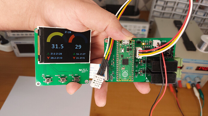
In this article/video, I used a Pico board, a digital SHTC3 sensor, and a 2.4” colorful TFT display to build a graphical temperature and humidity measurement/control unit that can be used to monitor the home, workplace, indoor garden, devices … etc. The board was also equipped with two Relays that allow the user to set the cooling/heating limits and adjust the parameters in the GUI.

The trickiest part of this project was the Pico code. I used the Pico C/C++ SDK library and invested a significant amount of time in designing the GUI and debugging the code. I should confess it was not an easy task.

To design the schematic and PCB, I used Altium designer 22 and installed the missing component libraries using Altium’s manufacturer part search. By using the Octopart website, I was able to quickly gather the necessary component information and generate the BOM. Finally, to get high-quality fabricated boards, I sent the Gerber files to PCBWay.

It’s a cool piece of hardware for anyone, so let’s get started :slight_smile:

https://www.youtube.com/watch?v=qtmLA5JVBaA

2 Likes

Cool,thanks for sharing. I have two questions:

  • Have you uploaded the project somewhere. I’d also like to make some experiments with RP Pico and your project would be a great starting point.
  • Do you see a way to improve the performance?

You’re welcome.

This project was designed for somebody and I am not allowed to share the code publicly (compiled file is available), but I will answer questions here or on YouTube. For a professional like you such things are a piece of cake, just try to compile a simple Pico project using the VsCode and Pico SDK. Then simply transfer your functions and replace your hardware functions with Pico SDK functions. That’s it.

Yes, there is a room for improvement. Now the Relays’ actions are based on the temperature, it should be switched to humidity as well or I should implement two extra Relays to simultaneously control both the temperature and humidity. for devices like an egg incubator, … etc.

Okay, thanks.

By improving the performance I meant higher FPS. Do you know what is current limit? MCU speed, memory speed, SPI clock, etc?

Pico MCU speed is default. I think it is more than 130MHz.

Connection interface between Pico and TFT is SPI and the SPI clock speed is 5MHz, however I personally refresh the screen every 1 second. because sensor speed is lower than this (around 5 second), so 1 second tick is the refresh action. if you mean the refresh speed between changing the screens that’s what I got with 5MHz SPI. I have used many Styles and I had to remove them and also remove the previous screen.
Current consumption of the Pico board is around 40mA. LCD backlight is around 130mA in full power. you can use some resistor in series to limit the backlight current if you like.

Still a few questions :slight_smile:

  • Have you enabled O2 or O3 optimization?
  • Do you sue SPI with DMA to make rendering and display refreshing parallel?
  • What is the size of the draw buffer(s)?
  1. I complied it with no optimization (Debug), The options are:
    2022-09-10_09-41-23

  2. I used the SPI without DMA, I think using DMA won’t affect this that much, 2.4" is not something that SPI can not handle

/* Size of the memory used by `lv_mem_alloc` in bytes (>= 2kB)*/
#  define LV_MEM_SIZE    (32U * 1024U)
static lv_color_t buf_1[LV_HOR_RES_MAX * 10];
lv_disp_buf_init(&disp_buf, buf_1, NULL, LV_HOR_RES_MAX * 10);

According to my experience Release mode would ~double the FPS. Could you give it a try.

On a 320x240 screen there are 75k pixels, meaning 150kB, meaning 1.2 Mbit. With a 5MHz SPI to refresh the display it takes 240ms. I don’t know the rendering time, but let’s say it’s 100ms in debug mode so 340ms in total → 3FPS. With DMA the 240ms display refresh and the 100ms rendering would happen in parallel, so it would be 240ms → 4FPS (still low, but 33% faster). However with 20MHz SPI, DMA, and Release build probably you could reach ~10 FPS.

So it’s 1/24 screen sized. In order to make LVGL work effectively 1/10 screen sized buffer (LV_HOR_RES_MAX * 10]) is recommended.


Let me know you are not interested in my advice and you are happy performance as it is. I’m just curios what could be made out from a Raspberry Pico.

of course I like it, why not. all of your comments are reasonable. I will test all and update you. I want to add also that the button delay (denouncing) was also added on the function, but any improvement in FPS is clear even by eye. also I was worried that increasing the SPI speed will cause instability problem because I used a 10cm flat cable, but I should test that also.

one thing before I go, the buffer size is already 1/10 (LV_HOR_RES_MAX * 10]) isn’t it?

That can be any issue, but worth a try. With ESP32 even 40MHz worked for me on a spiderweb of wires :slight_smile:

Nope. It’s 10 horizontal lines from the 240 → 1/24. 24 horizontal lines would be the 1/10 of 240.

increasing the SPI speed provided the maximum speed increase. now it works at 40MHz. there is no flickering and instability problem.
Release instead of debug showed some improvement, it was not that significant, but I certainly felt more speed.
I increased the 10 to 32 (lines) (in my case LV_HOR_RES_MAX = 320), I’m not sure about the speed effect. but it works without issue.

Great! Can you take a video to show the performance now?

Sure, I’ll do that as soon as possible. before that I have a question:

  1. Do you think driving the LCD using an 8Bit parallel GPIO bus is better than the SPI?
    Let’s say GPIO speed is around 50KHz (I have not tested it, it’s just an assumption).

  2. What about using a 16Bit parallel GPIO bus?

It can be calculated like this:

320x240 = 75k pixels = 150kB

With 50kHz is takes 150k/50k=3 sec to update the display. If it were 1MHz then 150k/1M = 150 ms.

So to really make a difference ~10MHz is required (resulting in 15ms).

In a driver I saw a great trick. In this modern MCUs there are registers to set/clear/toggle ports. I don’t know the exact name, but e.g. PORTA_CLR = 0x1 will clear the first bit.

So for a 8bit bus there are 256 different values that can be written. All you need is an array with 256 elements were you store values like:


/*     PORTA_CLR,     PORTA_SET,     PORTB_CLR,  PORTB_SET*/
/*0*/ {0x24,          0xA4,          0x11,       0x2a},
/*1*/ {0x35,          0x42,          0x31,       0xaa},
/*2*/ {0xa5,          0x12,          0xf0,       0x0e}, 
...

(the values are just random values and make no sense)

E.g. when you see that the value 23 needs to be written to parallel port, you can check the port clr/set values from the 23th element of the array and write them to the corresponding registers.

Let’s say all these with a WR strobe takes 15 instructions. On 130MHz it’s 130MHz/15 = 8.6MHz

Of course the best would if you could connect the data pins to e.g. PORTA[0..7] and could write the data with a single operation.

2 Likes