What do you want to achieve?
I want to display a simple UI using LVGL on an RGB LCD panel (ST7701, 480x854) with LTDC.
Specifically, I want to render a solid background and a small rectangle correctly without any distortion.
What have you tried so far?
-
Filling the framebuffer manually in
lcd_init()usinglcd_fill_color()works correctly (solid red screen is displayed without issues). -
LTDC is configured and running in RGB565 mode with external SRAM (FMC, 16-bit bus).
-
LVGL is initialized and a simple test function is executed to draw:
- A green background
- A blue rectangle
-
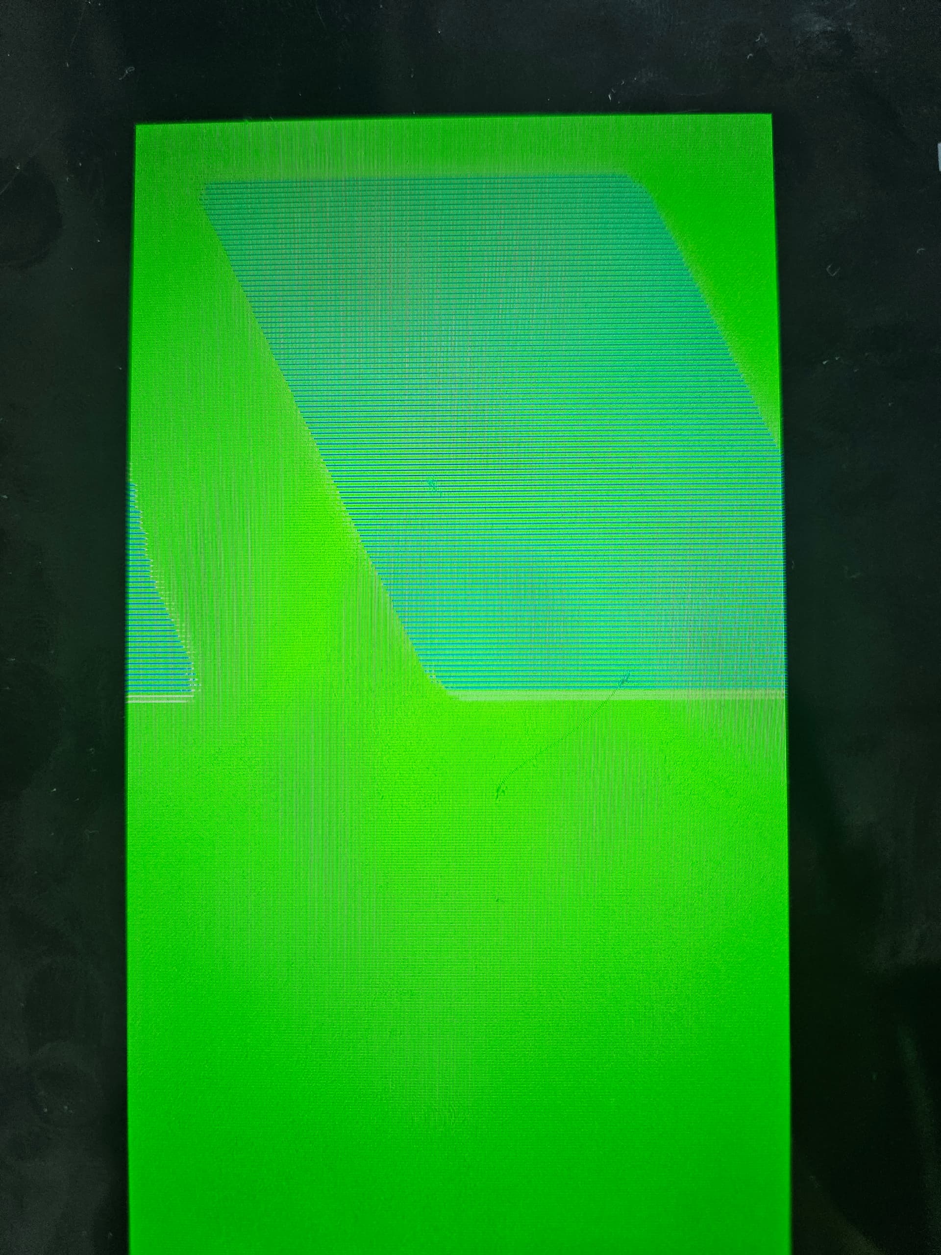
The background is rendered correctly.
-
However, the rectangle appears corrupted:
- It is diagonally shifted and looks sliced.
- It does not form a proper rectangle.
Additional debugging:
- I inspected the framebuffer memory directly using the debugger.
- Some memory locations do not contain the expected values based on coordinate calculations.
- The first pixel of the rectangle is correct (blue),
- But inside the rectangle, pixel values become inconsistent or misaligned.
- The corruption pattern appears diagonally across the screen.
Code to reproduce
/* You code here */
int main(void)
{
/* USER CODE BEGIN 1 /
/ USER CODE END 1 */
/* MPU Configuration--------------------------------------------------------*/
MPU_Config();
/* Enable the CPU Cache */
/* Enable I-Cache---------------------------------------------------------*/
SCB_EnableICache();
/* Enable D-Cache---------------------------------------------------------*/
SCB_EnableDCache();
/* MCU Configuration--------------------------------------------------------*/
/* Reset of all peripherals, Initializes the Flash interface and the Systick. */
HAL_Init();
/* USER CODE BEGIN Init /
/ USER CODE END Init */
/* Configure the system clock */
SystemClock_Config();
/* USER CODE BEGIN SysInit */
/* USER CODE END SysInit */
/* Initialize all configured peripherals /
MX_GPIO_Init();
MX_FMC_Init();
MX_LTDC_Init();
MX_QUADSPI_Init();
MX_UART5_Init();
MX_USART1_UART_Init();
MX_TIM4_Init();
/ USER CODE BEGIN 2 */
lv_init();
lcd_init();
// lv_port_disp_init();
// ── 테스트 UI
// lv_obj_t *label = lv_label_create(lv_scr_act());
// lv_label_set_text(label, “Hello, LVGL!”);
// lv_obj_center(label);
// lv_demo_widgets();
lvgl_simple_test();
/* USER CODE END 2 */
/* Infinite loop /
/ USER CODE BEGIN WHILE */
while (1)
{
lv_task_handler();
HAL_Delay(1);
/* USER CODE END WHILE */

/* USER CODE BEGIN 3 */
}
/* USER CODE END 3 */
}
void lcd_init(void)
{
GPIO_InitTypeDef GPIO_InitStruct = {0};
/* PC10(CLK), PC12(MOSI)를 SPI3 AF에서 GPIO Output으로 재설정 */
GPIO_InitStruct.Pin   = LCD_SPI_CLK_Pin | LCD_SPI_MOSI_Pin;
GPIO_InitStruct.Mode  = GPIO_MODE_OUTPUT_PP;
GPIO_InitStruct.Pull  = GPIO_NOPULL;
GPIO_InitStruct.Speed = GPIO_SPEED_FREQ_HIGH;
HAL_GPIO_Init(GPIOC, &GPIO_InitStruct);

// ✅ 두 레이어 모두 검정으로 초기화
memset((void *)0x60000000, 0x00, 480 * 854 * 2);
memset((void *)0x60100000, 0x00, 480 * 854 * 2);

// 1. 프레임버퍼에 RED 미리 채워두기 (ST7701 활성화 시 바로 표시)
lcd_fill_color(LCD_COLOR_RED);

// 2. ST7701 리셋
lcd_reset();

// 3. ST7701 초기화
lcd_config();

// 4. 백라이트 켜기
lcd_backlight_set(LCD_BL_MAX);

void * fb1 = (void *)LCD_FB_LAYER0;   // ⚠️ SRAM 주소로 수정
void * fb2 = (void *)LCD_FB_LAYER1;   // ⚠️ SRAM 주소로 수정

lv_display_t * disp = lv_st_ltdc_create_direct(fb1, fb2, 0);
}
void lvgl_simple_test(void)
{
// LVGL 객체로 그리기 (FB 직접 접근 X)
lv_obj_t *scr = lv_screen_active();
lv_obj_set_style_bg_color(scr, lv_color_hex(0x00FF00), 0);
lv_obj_set_style_bg_opa(scr, LV_OPA_COVER, 0);
lv_obj_t *box = lv_obj_create(scr);
lv_obj_set_size(box, 100, 100);
lv_obj_set_pos(box, 10, 10);
lv_obj_set_style_bg_color(box, lv_color_hex(0x0000FF), 0);
}
Screenshot and/or video
- The background is displayed correctly.
- The rectangle appears as diagonal lines or fragmented slices instead of a solid block.
Environment
- MCU/MPU/Board: STM32H743ZIT6 + External SRAM (FMC, 2MB) + ST7701 RGB LCD (480x854)
- LVGL version: 9.3