I also don’t know if you really need 1hz resolution on the frequencies. I am sure we can do some bit shifting of the numbers to change the precision and to do the math instead of using division.
That uses the RMT and the PCNT to measure frequency accurately.
Here is an example for how to use it.
Very interesting. That particular project is written for an older version of ESP-IDF so I’d need to update it. But, it kind of looks like it requires a long period before pitch detection would work. I tried some code for the Pulse Counter and RMT myself and even had a hex inverter sending in 0-3.3V pulses, but couldn’t ever get things to trigger properly.
I’m wondering now about using a Hex Inverter with a Schmidtt Trigger. The problem though might be that when the input signal drops below 60mV, the hex inverter will stop working.
You should be able to use a 2N2222 transistor to bump up the voltage coming in from the guitar so the GPIO will read a change properly. I don’t know off the top of my head what the ESP32’s voltage threashold is for a GPIO to read an “on” state For some reason the number 1.3v is what is what is coming to mind but I could be wrong. Guitars typically operate in the 0.1 to 1.0 range from what I have been reading. so that needs to be stepped up. you do not need to use something as complicated as an op amp if the only thing we care about is measuring the time between on and off so something that simply changes from 0v to 3.3v is all that is needed. You want something that will trigger an on state at a really low input voltage and I believe that the 2N2222 will do just that.
I am a big fan of the K.I.S.S. method. Keep it stupid simple.
You can use the ADC like you are doing but in all reality ADC numbers don’t mean a hill of beans because that is amplitude which is not the metric you are wanting to look at. You would need to pick an ADC value that would cause the time measurement to start and stop when it crossed that threshold in other direction. This would not be an ideal thing to use because you would not be able to use interrupts to do it and the built in continuous reading of the ADC is only going to signal you when the buffer is full so there will be a lag caused by the buffer needing to get filled. That would leave polling and the problem there is it would consume one of the processor cores to achieve.
achieving a read speed that will handle the frequencies a guitar will produce is not going to be an issue using interrupts. This is how it is done when working with displays and reading registers. it is able to handle up to 120mhz SPI without any issue so guitar frequencies should be a non issue. we just need to turn that analog signal into a binary on and off and that needs to be done if the voltage coming from the guitar passes a specific threshold. The sensitivity of the ESP32 is not going to be enough to achieve that on it’s own. You can use the op amp to do it so long as the op amp really drives the input signal up, like 0.05V would need to become 2.0v. You would need to clamp the output voltage from the op amp to 3.3v. You can achieve a binary on\off at 3.3v from a low voltage source using a transistor and some resistors. That will also take care of the clamping at the same time.
Yeah, one nice thing about the current ADC implementation is that it is extremely fast. The zero-crossing pitch detection I have only needs a few cycles of the incoming signal to detect a frequency. The difficulty is that I’m not too well versed with the electronics side. I think a simple Schmitt Trigger would work to create pulse information. I’m trying to model it up in LTspice using 2N3904 (since I have some on hand I could breadboard it out).
I wonder if something like this would work? The only thing I don’t have is a 1N4728A 3.3V Zener Diode.
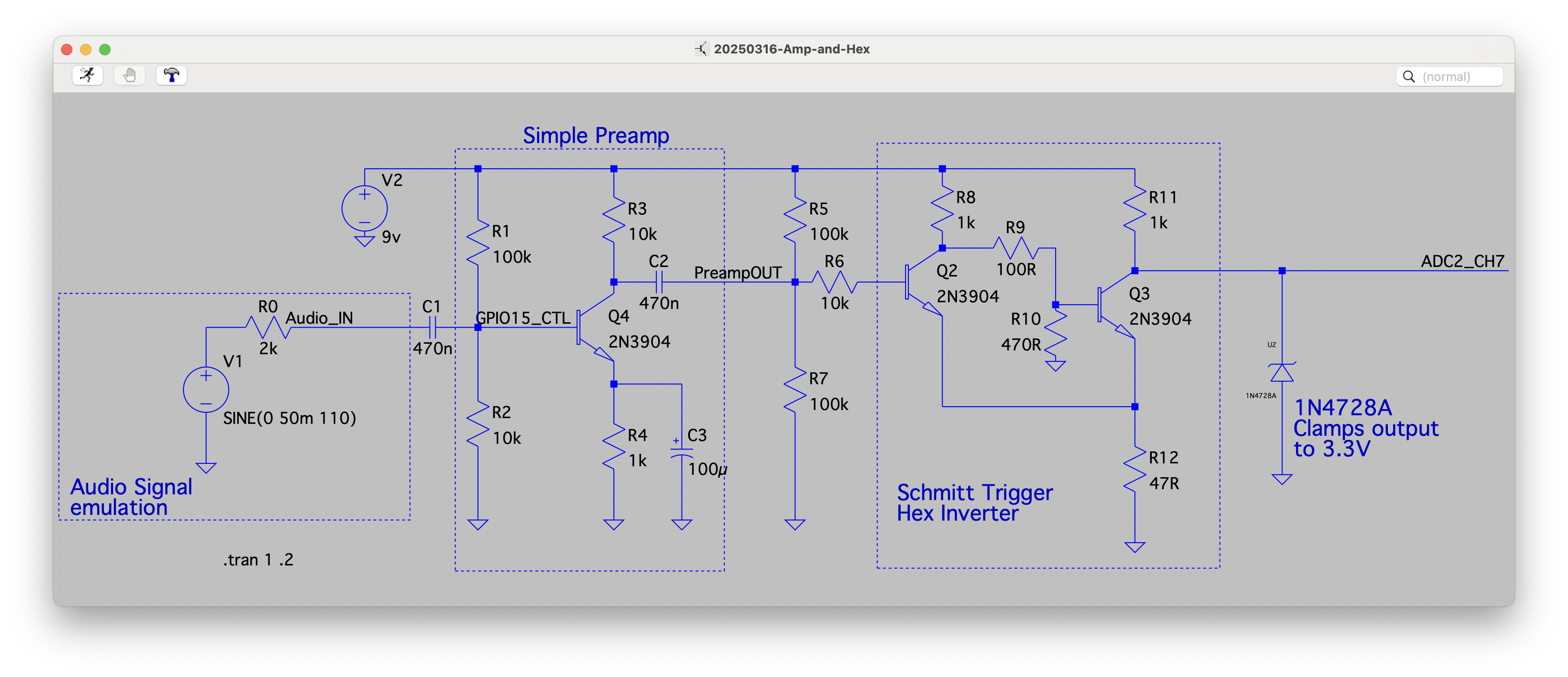
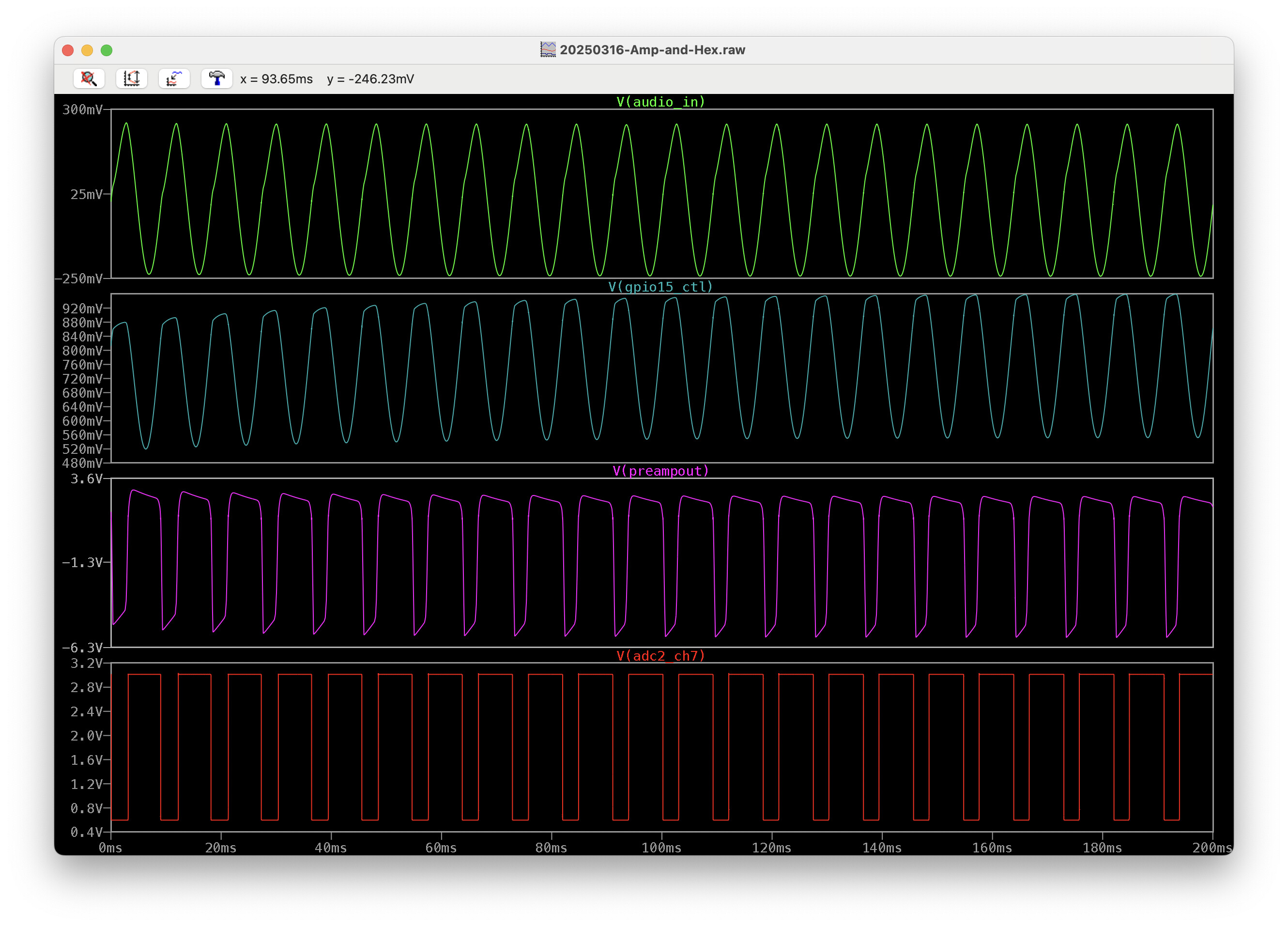
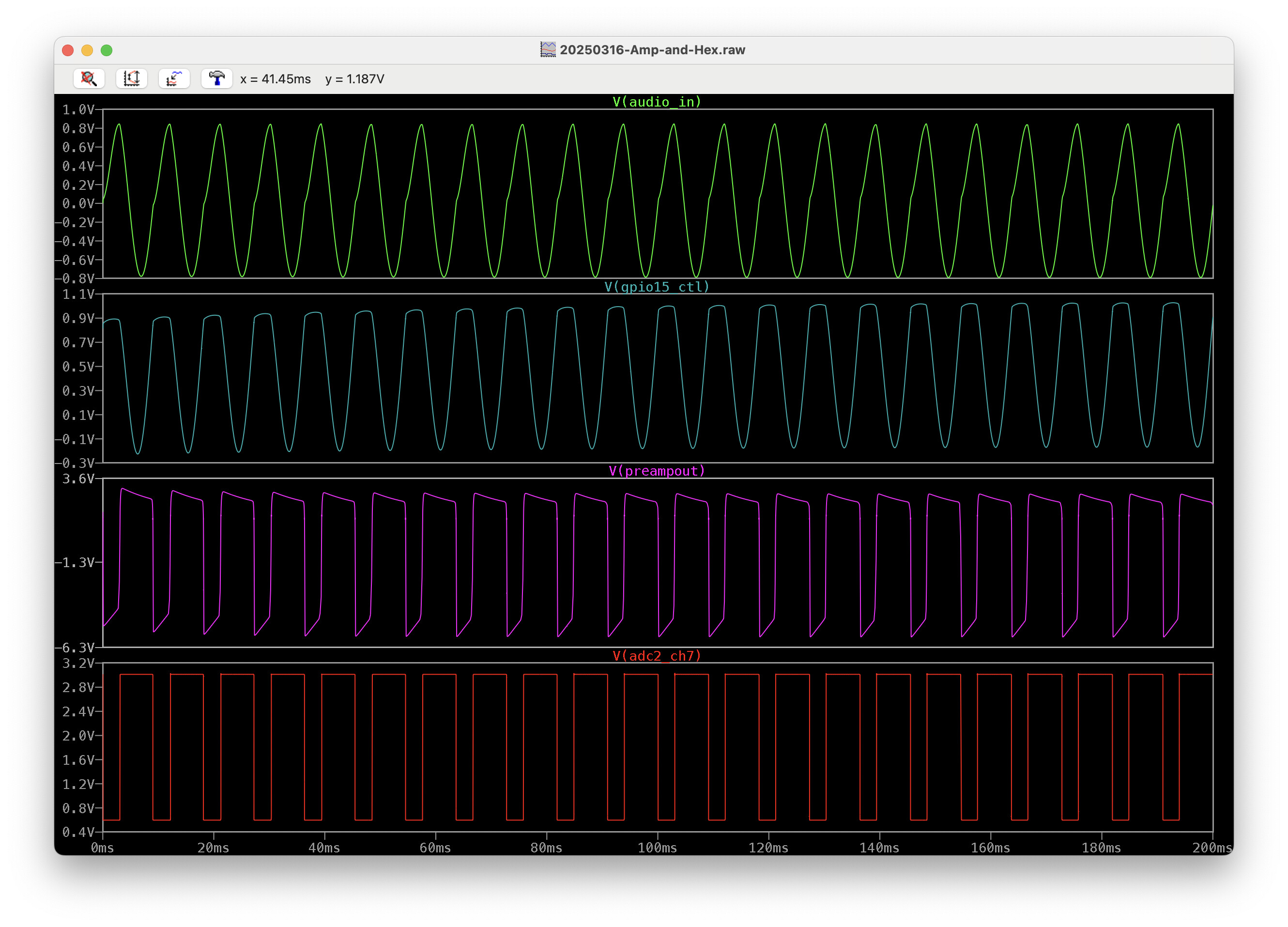
I would have to use both GPIO15 and GPIO18. GPIO18 would be the ADC line where I read the frequency information from the square waves. But, since the Schmitt Trigger will send values as low as 20mA input, I’d need to tie into the incoming signal (shown at GPIO15_CTL on the schematic) to use it as a noise gate/threshold to know when to stop interpreting the signal for frequency information otherwise, I’d probably get frequency detection on noise.
Here’s what it looks like with 20mA, 100mA, 300mA and 1000mA input:
Too complex with the circuit. You need to go basic with it.
Remember the K.I.S.S. method. don’t need to go overly complex with it.
That circuit is an example and I am sure it will not be correct but it should give you some ideas.
The only thing you are looking to do is go 3.3V when the voltage from the guitar is higher than 0v. Level shifting is all you are doing. Once you get the level shifting in place measuring the frequency is a snap to do and it can be done with ISR’s that only trigger when the voltage on the GPIO goes up and when it does back down. This will keep the amount of processing to only what is needed. You could technically react with a single measurement. You would not need to read and average values in order to get the frequency. It’s just a time measurement from when the voltage on the GPIO transitions from one state to the next.
You don’t even need to have a perfect squared off signal going to the GPIO. Not unless you are trying to be accurate to 1hz which I believe would be insane to do. 100hz yeah i can see. You could even argue for 50hz and that would be damned close to audiophile ears to hear a 50hz difference that is not below 120hz and even at those frequencies it’s more feeling then hearing. Once you get above 300hz to hear a 50hz change, most people are not going to be able to do. 1hz, not a chance in hell a person would hear that kind of a difference.
What kind of a frequency range are you wanting to target? something like 200hz to 15k??
What is the precision you are looking at get?
get an o-scope attached to the guitar output directly. No other electronics. see what you are getting for voltage readings from “noise”.
What I actually suggest doing is adding a UI control for input gain and using a GPIO to control the cutoff voltage coming from the guitar. Your circuit should not be consuming much in the way of current from the guitar. ideally you do not want it to because that would cause the voltage to drop and it would alter what you are getting for a reading.
I am not a wizard as circuits either. I know enough to light things on fire. LOL… I know enough to design and build simple stuff. What you are dealing with specifically if above my pay grade. IDK how you go about level shifting an AC voltage to a binary DC signal.
Yeah, I’m asking for more details on the All About Circuits forum. There’s definitely gonna be a better way to do this.
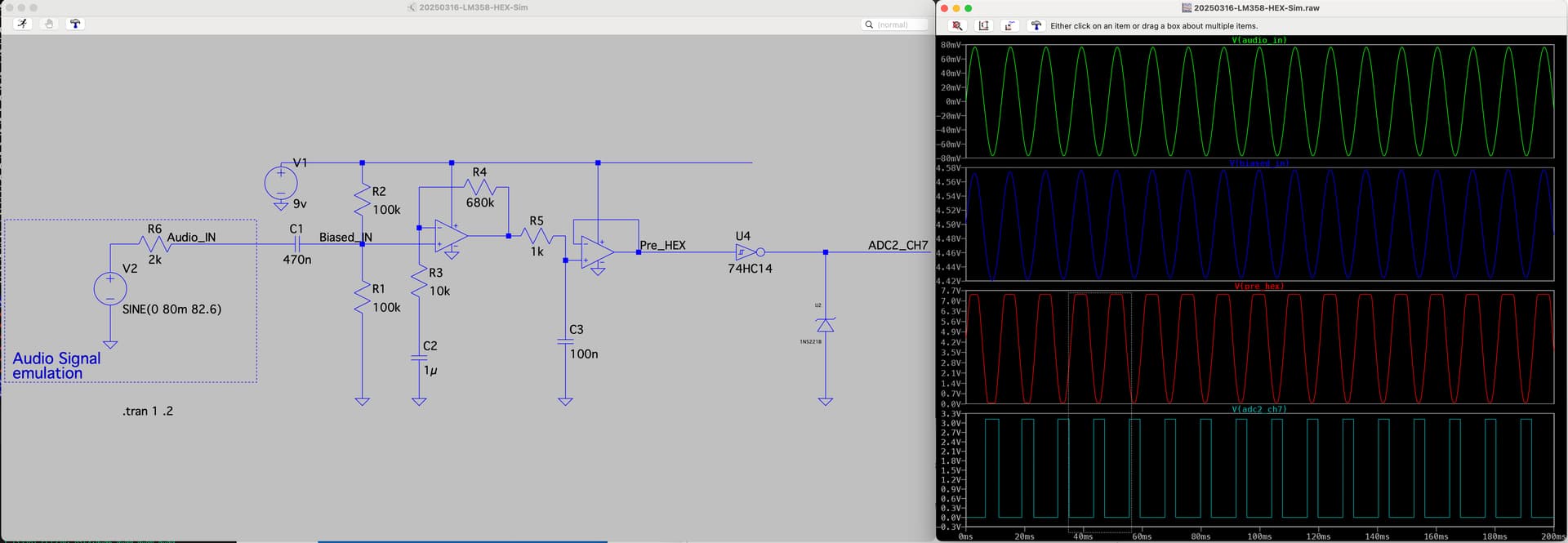
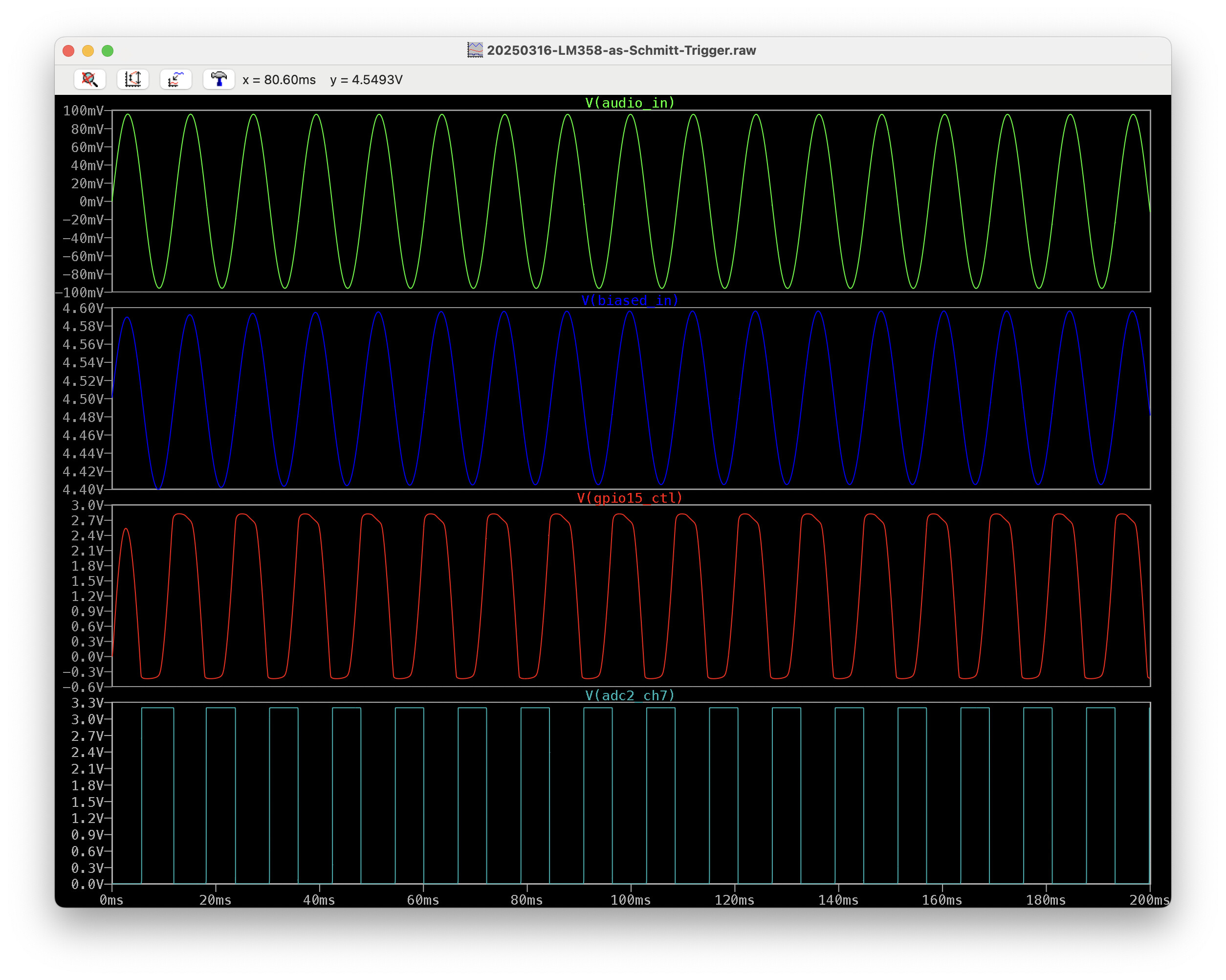
Ok, so we already have an LM358 op amp in the circuit already and it turns out we can use the 1st half of it to amplify the guitar signal and then use the 2nd half as a Schmitt trigger to output a nice square wave. I’ll get a couple of 3.3V Zener diodes and modify our current PCB and try this out tomorrow:
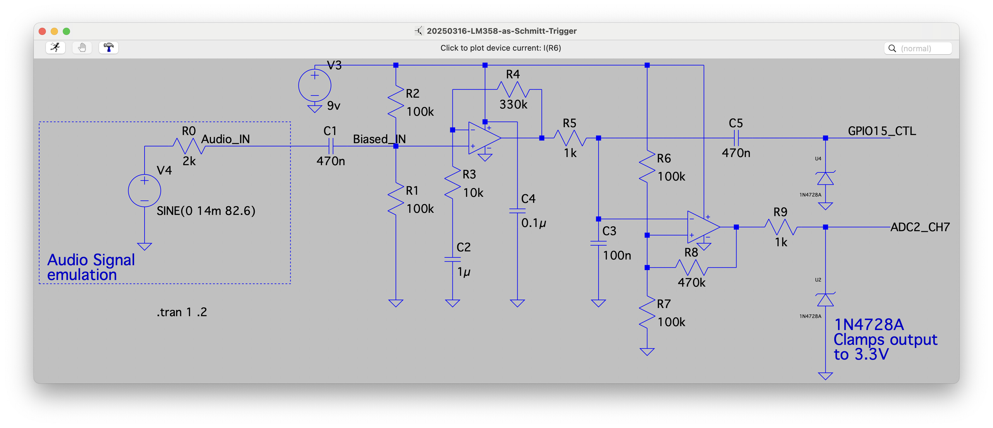
It outputs a square wave all the way down to 14mV input (in LTspice simulation) and it handles larger input voltages as well so it should be able to handle about any guitar pickup. The quiescent noise level bounces around 8-32mV so it’ll be interesting to see whether I’ll need to use GPIO15_CTL and read in the analog signal level as a noise gate (to turn frequency detection off when it gets too low).
Hopefully, this solution will give us better jitter-free accuracy. It definitely looks hopeful.
Oh without a doubt there is going to be. The trick is to keep is as simple as possible, clean as possible, and cheap as possible
-3.0 to 3.0 AC volts input converted to 0.0 “OR” 3.0 DC volts output (binary) with an adjustable input threshold where any volts above that line would output 3.0 and anything below it would output 0.0.
The adjustment would be nice because you could filter the low end noise out and that line is going to depend on where the user has the gain set on their guitar. so if you are like Marty and you like to roll the gains all the way up that cut off would need to be adjusted to account for the increased input.
I cannot think of a better way to explain it. The only reference that is available is a ground reference from the guitar. That’s where the hard part is going to be I believe.
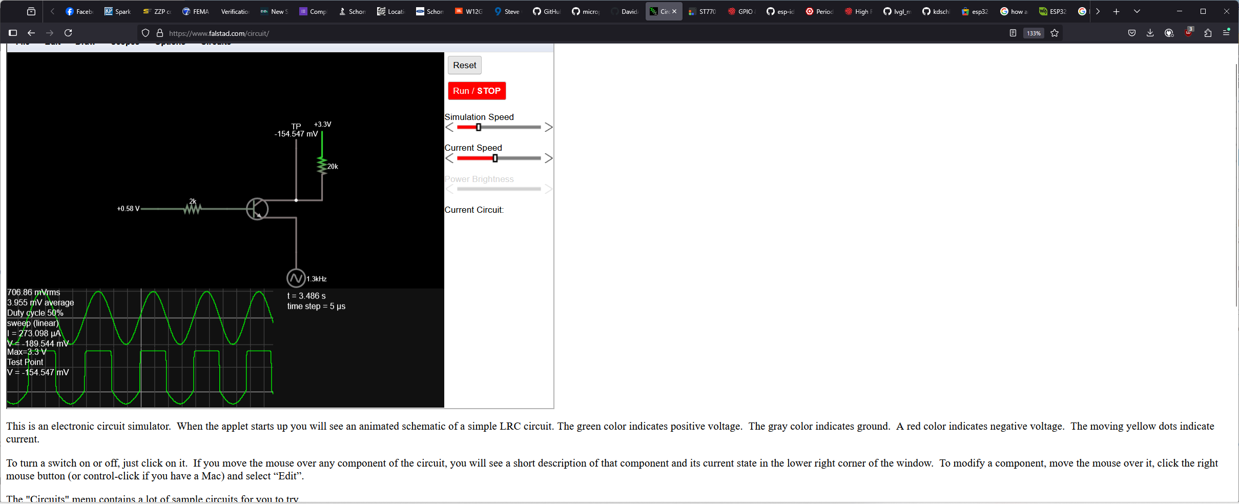
Here is a thought.
Add a 12 bit I2C DAC and loop it around to be the input for the NPN transistor so the user can control the voltage cutoff.
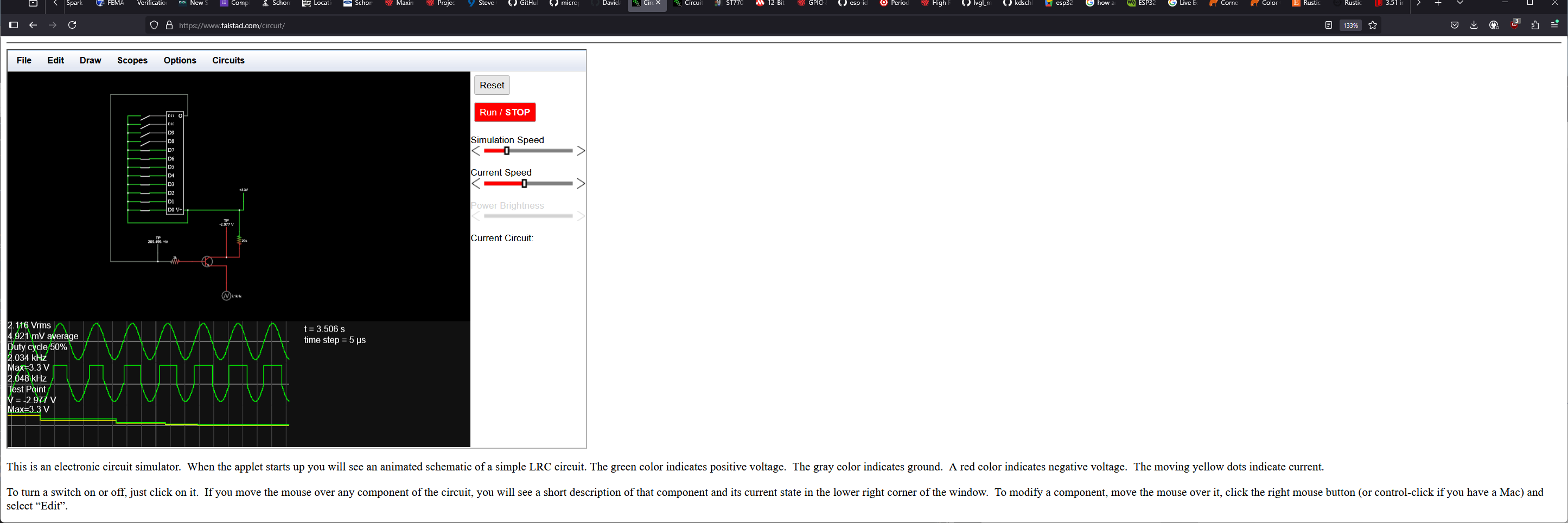
If you look at the middle scope that is the output from the NPN. The bottom scope is the output voltage from the DAC and the top is a frequency sweep set to a maximum of 3V output.
If you notice as the output voltage form the DAC increases the binary output from the NPN changes. The time between transitions gets smaller. That’s your noise filter. and it would be user adjustable from the UI. IDK if that would work or not but if it could be done that would be a nice feature to have.
This is where a DAC would come into play. The ESP32_S3 doesn’t have a DAC built into it. But you already have I2C broken out and available to you. adding a DAC could be something that is an add-on component and it could be detected on startup. All that would need to be done is an I2C scan to see what addresses are connected and if it’s connected then it would add the controls to the UI for adjusting. If it’s not connected then no additional control would be added and there would not be any noise filter. use a simple 6pin JST connector that has a loop plugged into it so when the DAC is not installed it would make the connection need for it to operate without a filter and when adding the DAC unplug the loop and plug in the DAC instead. That would connect the 5 lines needed for the DAC leaving the 6th pin which would be the looped connection disconnected.
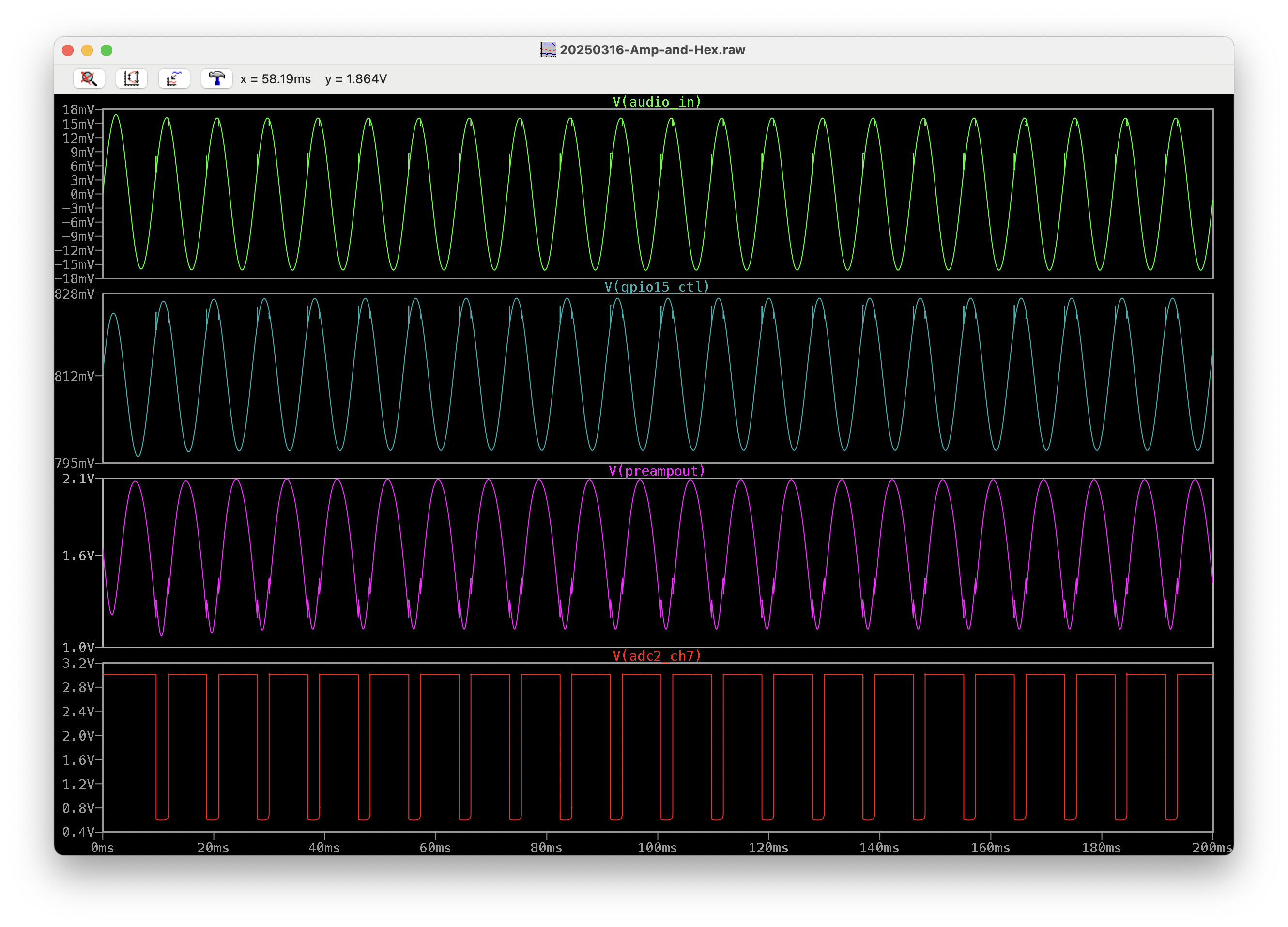
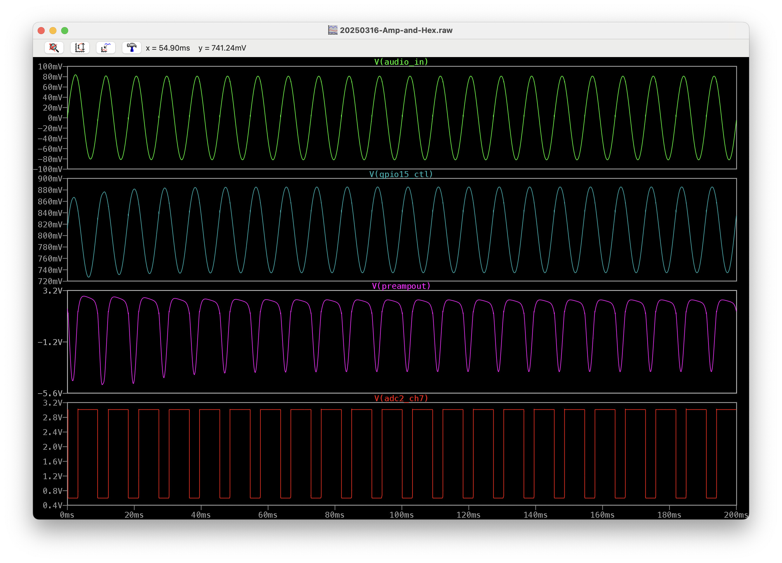
Turns out my experiment with converting it to a square wave/digital signal didn’t have the best result. My schmitt trigger didn’t trigger for long enough and the tuning period tapered off too quickly. So, it’s still better to use the LM358’s two stages of amplification and them clamp them with a 3.3V Zener. Here’s how it’s working so far. I left the LVGL diagnostics running so you can see that it’s working really quickly:
are you still using the ADC?
Yes. Still using ADC. I can’t yet figure out how to use PCNT or RMT to interpret the incoming signals.
Use my code example for interrupts and a simple binary trigger. You could actually do the frequency calculation right in the interrupt if you wanted using only the set time stamp from the last time the interrupt was called. I don’t really see a need for you to have to take multiple samples to figure out what the frequency is.
I am using like this:
esp_register_freertos_tick_hook(lv_tick_task);

static void IRAM_ATTR lv_tick_task()
{
    lv_tick_inc( pdMS_TO_TICKS( 1 ) );

    static bool flag = false;
    static uint32_t counter = 0;

    counter++;
    if( counter == 500 )
    {
        counter = 0;

        flag = !flag;
        if(flag)
            gpio_set_level( (gpio_num_t)MY_LED_IO_47, 1 );
        else
            gpio_set_level( (gpio_num_t)MY_LED_IO_47, 0 );
    }
}
Is the time accurate using the freertos tick hook ?
Yes, it might be okay. It’s still a software timer though so it cannot be really time accurate. I think FreeRTOS timing is also based on some sort of hardware timer somehwere, I would recommend looking into an interrupt on hardware timer instead if your device has any left.
1 Like
i implemented a gptimer for this.
Thank’s.
Hello, is there a final version of the code? I am having optimization issues in the demo.
Sorry. I abandoned the 460x640 in favor of the 240x320 because of performance issues.