With my guitar that has humbucker pickups in it I see it reach 2V on a loud strum. It’s going through an op amp circuit and getting amplified to get to 2V. So I think we’re safe in staying with the ADC_ATTEN_DB_12 setting.
if you are hitting 2V max then I would drop it down to a 6 DB atten. this will give you more of a range on the ADC values that are returned. It also removes any voltage changes on the power supply from skewing your values.
That’s my recommendation that has good reasoning for it.
Ok, I just figured out how to do ADC calibration code with ESP-IDF 5.3.2. It doesn’t really seem to do much of anything when I use calibrated values (doesn’t help tuning stability/jitteriness/detection).
Also, I’m a little confused on the 6dB attenuation as opposed to 12dB attenuation.
In both cases, I see raw ADC values between 0 and 4095. Going from 12 dB attenuation to 6 dB attenuation doesn’t seem to improve any pitch detection or jitteriness. They both seem to perform exactly the same way. Both are extremely fast pitch detection. What am I missing?
If they are both pegging at 4095 then you are at or above 3.3v at the GPIO for the guitar.
if that is the case then you need to put a voltage divider on it and get that number down to 1.6 to 1.7 volts.
the reason why I say you should get a divider on it is in the off chance you get someone that has a guitar that has a higher output. if you can cut the 3.3V in half then if the output from the guitar is 5V you will be cutting it down to 2.5 which will keep the MCU from getting toasted.
call it a sanity check if you want. It’s a good idea to set things up so that you have a reduced chance of something blowing up.
I will put an oscilloscope on it tomorrow and maybe that will be a little more accurate or give me a better picture of what’s going on.
OK, I confirmed with my telescope that it’s a bit high. I’ve worked up a model in LT spice where I can use the 3.3 V supply from the ESP 32 and a couple of diodes to clip the Signal so it won’t be above 3.3 V. That should work great because I don’t need to have a clean audio signal. I just need zero crossings to do pitch detection.
Thanks for the extra push to keep digging on this!
I will breadboard this idea later today.
Hey sometimes all that is needed is another set of eyes on it throwing some ideas out there on what can be done to make sure there are not going to be any issues. Last thing I want to see happen to ya is you release the project and then some people come back saying that they had some kind of a meltdown. Trying to locate where the issue is when that happens can be a hard thing to do. With something like a guitar I can see there not really being a standard when it comes to something like the voltage output from the guitar and I know there is definitely no standard as far as amplifiers go and their input voltage sensitivity. I have some experience in the world of audio and one of the things that has always been a tripping point is properly matching the input sensitivity of the amplifier properly to get the actual power that is being paid for. Using a 1V preout and plugging it into a 4 volt sensitive amplifier input doesn’t pair up well. So I can see where there might be cases where guitars outputs can vary greatly and then toss in there the type of guitar being used which would also have an impact on the output voltages that are seen… You gotta put a clamp on that voltage getting to the ESP32 otherwise things can go bad.
I do not believe you would ever see higher than 13v coming out of a guitar. I say 13v because that is the highest I have ever seen a preamplifier have for an output voltage. Highest I have ever seen an amplifier have for an input voltage is 8v. Now I am sure that there are probable some edge cases and custom gear where things may be higher but it is definitely not something that would be mainstream that’s for sure.
Before I retired what I did was I worked on vehicle electronics. Mostly in reverse engineering the systems in the cars so we could integrate aftermarket upgrades. Things like audio interfaces, transponder bypasses, things of that nature. I was involved in building an audio system for a vehicle that held the record for almost a decade for the worlds loudest car. 169.8dB. more than 12000 watts RMS of power coming from unregulated amplifiers, 16 dry cell batteries @2200 amps each, 300 amp 18v alternator and 10 subwoofers @ 15" diameter and were piston drivers. enclosure was made from 1/4" plate steel. Packed all of that stuff into an early 80’s VW Gulf. This was in the 1990’s when we did this. That was right around the time when all of the computer systems in vehicles started to really become more advanced and car manufacturers started putting data networks in cars. I worked with a lot of the aftermarket component manufacturers developing the interface modules used in vehicles. We really pushed the boundaries back then with the stuff we did, pushing what was possible in order to achieve the best possible sound in what is considered to be one of the hardest environments to do that. the large differences in vehicle construction and materials that are used inside of a vehicle coupled with some really tight spaces make it really hard.
One of the best sounding vehicles I put together was a 2004 GMC Yukon Denali. Total of 13 drivers in the car and 2 amplifiers that had 8 channels each. It was a stealth installation so not much was actually visible. I even went to the extent of building full ported enclosures inside of the front doors which had a total of 3 drivers in it that were mounted on axis to the center of the vehicle between the front seats.
Question about your setup. Guitars typically only have the phono plug correct? They create their own power from the pickup right? There is no power being passed into the guitar that can be used as a reference voltage right?. I am asking this because if it does have an input power that the output power is derived from then you could use a level shifter to normalize the output voltage from the guitar to a 3.3v signal. If this reference voltage is not available then you would need to know what the maximum output voltage could be from a guitar and a voltage divider might be the only real way to get it under the 3.3v.
From a quick search it is as I said it is. The numbers are all over the place. One article I read says 24V peak to peak is achievable. Technically speaking there is no actual maximum because of how pickups are designed. That article said that most playing falls into the 100mv to 200mv area. Kind of hard to design something that will be sensitive enough to handle that low a voltage range and also be robust enough to work at a 12v input. You may have to get a 24 bit ADC IC to handle it.
Did everyone involved lose their hearing!? That is simultaneously amazing and crazy! ![]()
I think our best plan of attack for this is to use the preamp we have on the PCB we built to amplify the guitar signal (it generally clips, which is actually good for zero-crossing pitch detection) and then just make sure we clamp the outgoing voltage to 3.3V or lower. It should work. I’ll test it out in a few hours after taking care of some weekend errands.
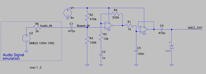
Ok, it looks like if I used a single 2.4V Zener Diode (a 1N5221), I could clamp the output around 2V.
Simulations:
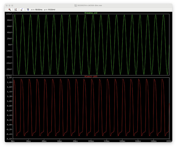
Here’s a 100mVAC guitar input (one of my teles outputs about max of 120mVAC):
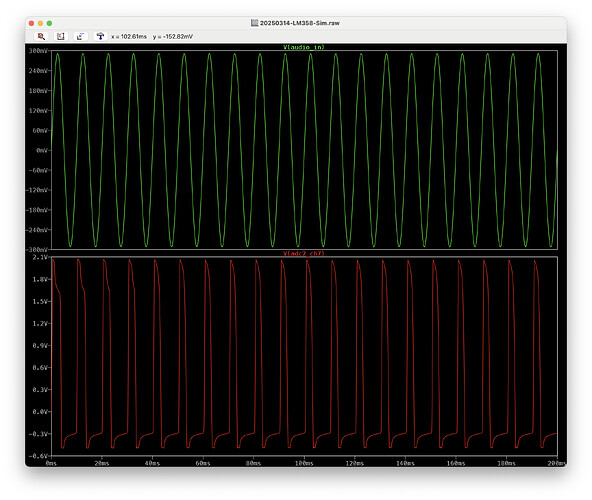
Here’s a 300mVAC guitar input (similar to one of my humbucking guitars):
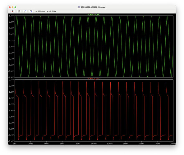
And, just to be crazy, here’s a 1VAC guitar input signal:
So, it seems like I could throw on a single 2.4V Zener diode and that’d work for pretty much any guitar that might plug into this, right? Again, I don’t care about a clean sine wave but am only interested in zero crossings. In my early experiments making our preamp circuit go into clipping actually improved pitch detection.
Hearing protection was a must if sitting in the vehicle. And you had to hold the hearing protection firmly to your head when it was turned on. I can tell you that you could not breathe when in the var and it was turned on. The pressure inside of the vehicle was insane. At that point it’s not even about “loudness”, It’s actually all about what percentage of the air inside of the vehicle is able to be displaced by the cone movement of the woofers. Think air compressor. We actually plumbed 3 portable 10K BTU air conditioners to the vehicle to get the air as cold as possible inside of the enclosure and the cabin and to also remove any humidity in the air as well because dry cold air is denser than hot moist air. The cold air also helped with reducing the number of blown woofers which we typically would have at least 1 blow up. When they blow the sub actually ends up separating at the spider and the cone inverts and will tear around the outer suspension with the cone sometimes completely detaching and becoming a projectile typically hitting an occupant in the back of the head. Felt like someone smacking ya in the back of the head so it scared the crap outta the person when that would happen. There was so much current being drawn we had to turn the engine idle up to 3500 RPM’s to keep the engine from stalling. The alternator became so hard to turn that was the only way we were able to keep the strain from causing the RPM’s to drop to the point where the spark plug coil would not get enough voltage. At the 3500 RPM when we turned on the system the RPM would drop to about 400.
I worked with Audio Control to design a time alignment circuit that all 10 amplifiers were connected to and that time alignment would alter the phase and a delay in the output signal. The enclosure was a V on it’s side with all 10 subs inside of that V. 4 on top,m 4 on bottom and one on each side. The sube that were the deepest into the V would fire first then the ones on the side and then the ones at the outter edge. It basically created a ball of pressure that would get pushed out of the enclosure. This could be seen using an SPL meter and where the mic was placed inside of the vehicle.
out of question why are you even amplifying the signal coming for the guitar before attaching to the ESP32. If the output signal from the guitar doesn’t eclipse 3.3v then you are fine. Just clamp that voltage so it cannot possibly go over 3.3v no real need to amplify the signal. I would think that having a 12 bit resolution over a 0v to 3.3v range would be enough to do what you are looking to do. Even if most guitar signals are in the 0v to 1.0v range that would give you an 11 bit resolution or an ADC range of 0 to 1240
is that not enough resolution to do what you are wanting to do?
Yeah there was a lot of engineering that went into that vehicle. Those were the days.I had lots of fun then. Companies would give me equipment to use in my personal vehicle free of charge.
Ever seen one of these??
No I am not in the photo. That is some random image I pulled from the net. That amplifier was made as a joint thing between Crown and JBL. That amp would put out over 13,000 watts when a 1 ohm load was attached to it.
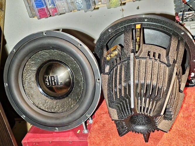
Ever seen these??
That’s a 12" subwoofer made by JBL. One of the best ever made. 4000 watt peak power, 91dB 1W@1m sensitivity, the cone was super light which is how they managed to get that high a sensitivity with a coil that was able to handle 4000 watts peak. The cone was a composite of Kevlar and pressed paper which made it light and really strong. When paired to a properly made enclosure those subs has fantastic sound to them. they were able to respond very fast and accurately even when a drummer would be hammering on that foot pedal for the bass drum.
man o man, the memories…
I will do some additional experiments to see if I can use less attenuation and just take a signal straight from the guitar but if I remember right, my earlier testing made it so it just wasn’t a strong enough consistent signal to keep it working the right way. Adding our own op amp-based preamp was a way we can keep the incoming signal nice and strong.
I’ve never seen those speakers before. Looks like a lot of fun!
Yup. With ADC attenuation set to 0 the signal from my Telecaster just isn’t enough to keep pitch detection reliably working for more than a second or so. I think the best option is amplifying into clipping and then just clamping to make sure we don’t exceed the ESP32’s limits.
I believe that with your specific use case the best solution is going to be to use the RMT on the ESP32. the only thing you are looking for is the frequency which is the spacing between the waves. This would be the reason why you don’t care if the signal becomes digital.
What the RMT will do it is will look at the incoming signal and it will clip it for you to make that squared off pattern you want. The best part about the RMT is it is going to return an array of durations which is how long the signal is on for and how long the signal is off for. This is ultimately the information you want to know right?
Wow, now that is thinking outside the box! I had to go look up what RMT even is (Remote Control Transceiver (RMT) - ESP32 - — ESP-IDF Programming Guide v5.3.2 documentation).
What would the hardware look like? Would I still just send in a clipped signal that’s 3.3V or less and it wouldn’t have to be a perfect square wave or anything?
Also, would I set up an RX channel with a frequency_hz as the sample rate that I’d want to sample readings? I’m not sure what the duty_cycle would need to be set to.
rmt_carrier_config_t rx_carrier_cfg = {
    .duty_cycle = 0.33,                 // duty cycle 33%
    .frequency_hz = 25000,              // 25 KHz carrier, should be smaller than the transmitter's carrier frequency
    .flags.polarity_active_low = false, // the carrier is modulated to high level
};
// demodulate carrier from RX channel
ESP_ERROR_CHECK(rmt_apply_carrier(rx_chan, &rx_carrier_cfg));
With the RMT I am not sure if it will allow you to detect the frequency. That is the one thing you are going to have to see if it is able to do. If you can have it detect the frequency then it’s all gravy train on biscuit wheels from there. If it is not able to detect frequency then what you need to do from there is ditch using the ADC and do with a straight up digital reading. The only thing you care about is the frequency which you are able to detect using just a regular digital IO. That is something that you can use a really simply transistor to latch and unlatch using the low voltage from the guitar. No need to have any kind of “amplification” and reading ADC values. You can use a high priority ISR on the core not running LVGL that will trigger at the rising edge and the falling edge so you can time the signals using the CPU clock clock cycles. Very accurate way to capture the frequency (pitch). Place the callback function in IRAM so it executes a hell of a lot faster. create…
This code is pseudo code and it has not been tested. It should provide you with microsecond time precision when sampling. The calculations are very simple to go from microsecond duration to frequency. I am using FreeRTOS Event Groups to signal when 10 time samples have been collected. The task that converts the collected samples to frequencies is stalled when waiting for the buffer to get filled and the ISR will not access the buffer until it is not being accessed by the task converting the collected durations.
I have written it so if the buffer is being accessed by the task the ISR just drops the current sample. You can optionally have a second buffer to place the “dropped” samples into if you want and then copy them into the samples buffer once the task is done accessing that buffer. This way you will not drop any samples.
This code is for using a digital IO to calculate the frequencies from. It is much easier for you to use a simple transistor and a pull down to trigger the GPIO. This would take care of the voltage clamping and any kind of jitter issues that you get when using an ADC.
#include <stdlib.h>
#include <inttypes.h>
#include "esp_timer.h"
#include "freertos/FreeRTOS.h"
#include "freertos/task.h"
#include "freertos/event_groups.h"
#include "freertos/idf_additions.h"
#include "driver/gpio.h"


#define INPUT_GPIO 15
#define INPUT_GPIO_MASK = (1ULL << INPUT_GPIO)

#define BIT_0 (1 << 0)

typedef struct {
    EventGroupHandle_t handle;
    StaticEventGroup_t buffer;
} event_t ;


void event_init(event_t *event)
{
    event->handle = xEventGroupCreateStatic(&event->buffer);
}


void event_delete(event_t *event)
{
    xEventGroupSetBits(event->handle, BIT_0);
    vEventGroupDelete(event->handle);

}

void event_wait(event_t *event)
{
    xEventGroupWaitBits(event->handle, BIT_0, pdFALSE, pdTRUE, portMAX_DELAY);
}


bool event_isset(event_t *event)
{
    return (bool)(xEventGroupGetBits(event->handle) & BIT_0);
}


bool event_isset_from_isr(event_t *event)
{
    return (bool)(xEventGroupGetBitsFromISR(event->handle) & BIT_0);
}


void event_set(event_t *event)
{
    xEventGroupSetBits(event->handle, LCDBUS_BIT_0);
}


void event_clear(event_t *event)
{
    xEventGroupClearBits(event->handle, BIT_0);
}


void event_clear_from_isr(event_t *event)
{
    xEventGroupClearBitsFromISR(event->handle, BIT_0);
}


void event_set_from_isr(event_t *event)
{
    xEventGroupSetBitsFromISR(event->handle, BIT_0, pdFALSE);
}


event_t buf_ready_event;
event_init(&buf_ready_event);

int64_t start_time = esp_timer_get_time();
int64_t end_time = start_time;
int64_t time_diff;

int level;

uint8_t buf_count = 0;
int64_t buf[10];


static void IRAM_ATTR pin_isr_cb(void *args)
{
    end_time = esp_timer_get_time();
    time_diff = end_time - start_time;
    start_time = end_time;

    if (event_isset_from_isr(&buf_ready_event) {
        // skip this sample because the data is being accessed by a task.
        // We don't want to corrupt the memory
        return;
    }

    buf_count++;
    if (buf_count == 10) buf_count = 0;

    buf[buf_count] = time_diff;

    if (buf_count == 9) {
        // we have collected 10 samples so let the task know they can collect
        // the data to calculate the frequency
        event_set_from_isr(&buf_ready_event);
    }
}

// code below here you would run in a task onm the core that
// LVGL is not running on

gpio_config_t io_conf = {
    .intr_type = GPIO_INTR_ENABLE,
    .mode = GPIO_MODE_INPUT,
    .pin_bit_mask = INPUT_GPIO_MASK,
    // disable internal pull resistors
    .pull_down_en = 0,
    .pull_up_en = 0,
    // trigger ISR on the rising and the falling edge
    .intr_type = GPIO_INTR_ANYEDGE;
};

gpio_config(&io_conf);

gpio_install_isr_service(0);
gpio_isr_handler_add(INPUT_GPIO_MASK, pin_isr_cb, NULL);


int64_t samples[10];
uint32_t freqs[10];

while (1) {
    // wait indefinatly until the buffer is ready to be collected
    event_wait(&buf_ready_event);
    // now we can collect the data and know that mthe data is not going to
    // be accessed by the ISR
    memcpy(samples, buf, sizeof(int64_t) * 10);
    // signal the ISR so it will know that is can write to the buffer again
    event_clear(&buf_ready_event);

    for (int i=0;i<10;i++) {
        // 1 microsecond is 1000000hz so to calculate the frequency from
        // a microsecond measurement we use the simple equation below
        freqs[i] = (uint32_t)(1000000 / samples[i])
    }

    // do whatever it is that needs to be done to the frequencies

    // code loops back around to wait for the buffer to be filled
    // if it is not filled already
}
I was going to RLC encode the sample data so you would have + and - numbers that would be the length of time the pin was “on” and the length of time the pin was “off” and off would have had the negative numbers but I thought it really would not matter because we are dealing with an AC waveform converted to a binary signal and the “off” time can also be used to calculate the frequency just as much as the “on” time can be.
