Got rid of this by increasing the flash to 16MB in menuconfig.
Still getting this though:
E (416) lcd_panel.rgb: lcd_rgb_panel_alloc_frame_buffers(165): no mem for frame buffer
E (426) lcd_panel.rgb: esp_lcd_new_rgb_panel(353): alloc frame buffers failed
E (436) st7701_rgb: esp_lcd_new_panel_st7701_rgb(133): create RGB panel failed
I (446) LCD: esp_lcd_new_panel_st7701 returned: ESP_ERR_NO_MEM
I went and updated the menuconfig (sdkconfig) values to match my real project and it gets further but I’m getting a huge error. Trying to track it down:
OK so there a few things that are going to cause some big problems.
The first thing is the SPI2wire the display uses actually shares the pins with other SPI devices. So we cannot use the spi3wire component because that driver is a bitbang driver.
That means we need to write a custom display driver.
Because the CS pin for the display is attached to the io expander and not the ESP32 we cannot use the ESP-IDF’s internal handling of the cs pin for the SPI. we need to roll our own handling of the cs pins.
We have the same kind of an animal going on with the I2C as well. That is a shared bus with several devices so we need to manage access to the bus so we don’t end up with anything bumping heads.
Now you may not at this point in time be worried about using the SD Card reader or the mems sensor or the RTC. It is better to add the code now to be able to delicate bus access to the SPI bus and also the I2C bus. It is going to be easier to do it now then it would be to do it later on.
Now fret not. I have already written a custom display driver for you. Well I am working on it anywho.
Since I am up to my boys in it already with the display driver I may as well add the code that will do the rotation and dithering features. This is the code that will improve the performance of the RGB driver by quite a bit. Here is the catch tho. I know that you have some kind of a task that need to run to collect data from a GPIO. I know it is important for that task to read that pin extremely often. I am not 100% sure of what you are reading but I suspect it is going to be some kind of an analog signal. If that is the case then we might be able to use the continuous ADC feature that is built into the IDF. This feature will allow you to create a DMA buffer that will store the ADC readings. You can specify the frequency in which you want it to take samples form the pin. This is a non blocking function so once you set this up it will run without using the processor to collect the samples. We can hook in a callback that will get called in an interrupt if the sample buffer is full and optionally we can interrupt the sampling and check the buffer at any time there is some processor time available. If this will work for what you are wanting to do then we can use that RGB display driver code I wrote to get you some better performance from LVGL and the display.
Yes, on the 480x640 Waveshare 2.8", the “EBD4”, I am currently using continuous ADC1_CH3 on GPIO 4 to read an incoming guitar signal that’s gone through a pre-amp circuit. I’ve dedicated the entire 2nd CPU core just for ADC and pitch detection. It works like a champ.
I’ve been using the 1st CPU core for all the GPIO and GUI.
One question I’ve got is why not use the driver that Waveshare provided? The way I have it working (albeit slow FPS), it’s by using their driver.
I’m currently trying out the lower-res Waveshare 2.8 (240x320) display ESP32-S3, the “EBD2”. It doesn’t give me access to any of the ADC1 pins and so I’m trying to use an external ADS1015 chip over I2C to sample the guitar signal at 3.3kHz. I’m getting readings, but I need to fine-tune the speed/etc of how they work so my pitch detection code runs smoothly.
With the EBD2 device, I’ve got it hooked up using their provided driver files and esp_lvgl_port and the display is running fast.
If it turns out that I can get this external ADC to work well enough, that’ll be sufficient for this particular project. Hopefully I can either rule in or out that method today.
Unfortunately, the EBD2 doesn’t expose enough GPIO pins or I would have tried using an external ADC chip that uses SPI because I could make the sampling frequency much higher.
For your specific needs I recommend using something like the w32sc01-plus. It’s a 3.5" display at 320 x 480. It uses an 8 lane I8080 connection to the display IC and the display IC has GRAM so you won’t have to keep feeding a stream of data to the display like the one you have currently. It is going to be 8 times faster than an SPI display because it has the 8 lanes. It is also going to be faster than an equal sized 16 lane RGB display because the speed the data is able to transfer at is 80mhz and not 15mhz. 8 lanes at 80mhz has a theoretical speed of 10,000,000 bytes per second per lane. VS a 16 lane RGB which is 1,875,000 bytes per second per lane.
so with a frame being 307,200 bytes in size you can get a theoretical frame rate of 260 FPS vs RGB which is 97 FPS. Now these are not real world number and you will not get anywhere near these speeds. This is simply to show the kind of transfer speed difference even though the RGB display has twice as many lanes to transfer the data it is still slower. I have not yet messed around with MIPI DSI displays. Those are supposed to be able to get into the gigabit speeds per lane. They suffer the same fate as the RGB displays in that there is not usually any internal GRAM in the display IC so a constant stream needs to be sent from the MCU and that consumes a core in order to achieve that.
The w32sc01-plus doesn’t have a giant amount of RAM and that is the biggest things that can be limiting. But you also don’t need to create giant frame buffers either so you save a lot of memory use there.
gpio19: USB
gpio20: USB

gpio41: SD CS
gpio40: SD MOSI
gpio39: SD SCLK
gpio38: SD MISO

gpio35: Audio LRCK
gpio36: Audio BCLK
gpio37: Audio DOUT

gpio1: RS485 RXD
gpio2: RS485 RTS
gpio42: RS485 TXD

gpio45: LCD BL
gpio4: LCD/TP RESET
gpio0: LCD RS
gpio47: LCD WR
gpio48: LCD TE
gpio9: LCD D0
gpio46: LCD D1
gpio3: LCD D2
gpio8: LCD D3
gpio18: LCD D4
gpio17: LCD D5
gpio16: LCD D6
gpio15: LCD D7

gpio7: TP INT
gpio6: TP SDA
gpio5: TP SCL

gpio10: USER
gpio11: USER
gpio12: USER
gpio13: USER
gpio14: USER
gpio21: USER
so you get more pins available for use and you don’t have extra complexity of the IO expander. The I2C and the SPI are both broken out so you can add to the hose busses if you wanted to.
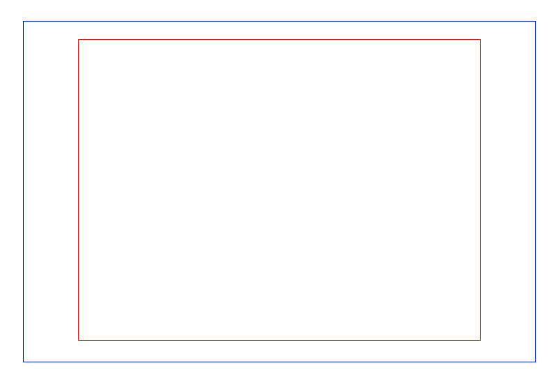
I know this is a slightly larger display than the 2.8" display that you were using. 3.5" is not that much larger a display.
The blue is the 3.5" display and the red is the 2.8" This is the actual viewing area size difference.
Well, darn. My experiments with an external ADS1015 with the EBD2 board aren’t working out very well. It’s not giving me reliable info on zero-crossings of an incoming audio signal and so EBD2 is going to be worthless because it doesn’t expose ADC1. Grr.
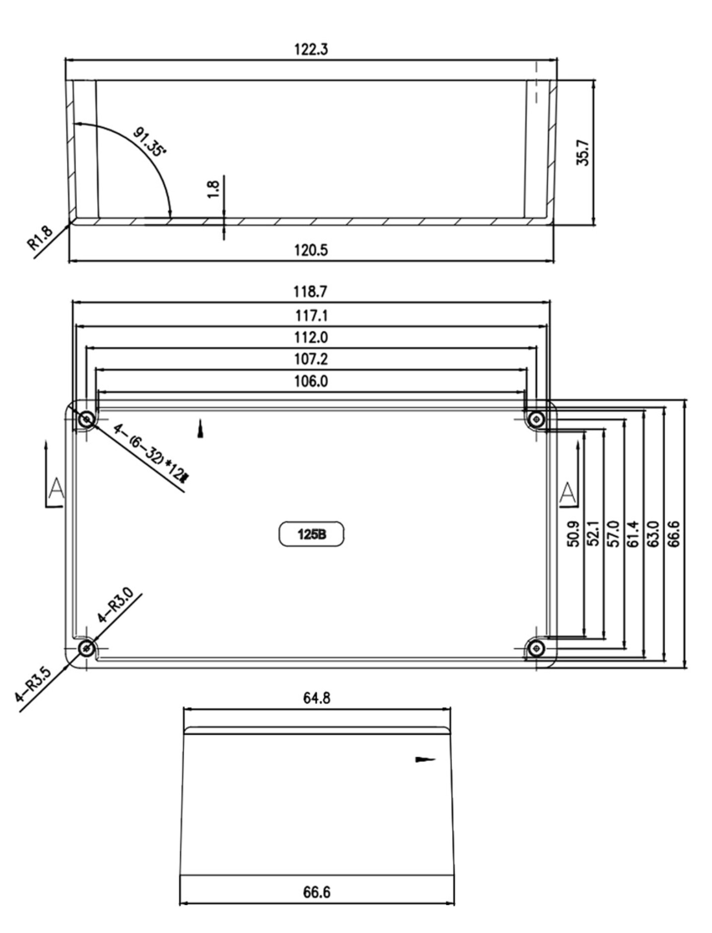
That’s also the total dimensions and not the dimensions of the actual display. The actual viewable display area is 49.56mm x 74.04mm. So you could cut an opening in the enclosure and mount the display to the back side. The extra “lip” around the edge of the display can be trimmed so it would fit into the enclosure and seeing as how the enclosure is aluminum cutting the opening would be easy to do. The use 4 flat head socket cap screws and some nuts to attach the display to the enclosure. Drill right through the plastic lip around the display as there is nothing there but plastic. Countersink the screws into the enclosure for a nice finish. That would be crazy easy to mount in that kind of an enclosure…
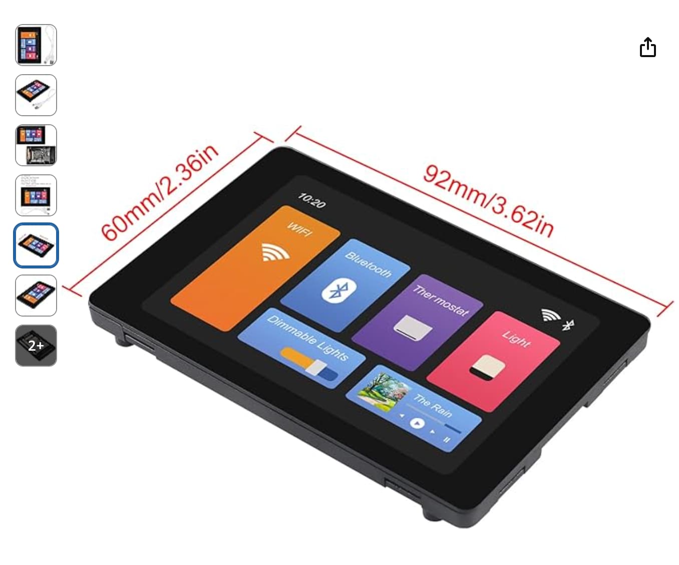
Another option you have is to use what is called a “Bar” Display… Take this one as an example. This is just an example that you can get displays that would be an almost perfect fit for that size enclosure.
That is still a 3.5" display except the aspect ratio is different.
You can fit upwards of a 4.5" display into that enclosure without an issue if you go with a bar style display. The tricky part is tracking down one that is the size you wanna go with and has an I8080 interface and not an RGB or DSI interface. You might need to do a little bit of PCB design which is not that hard to do and I would happy to lend a hand with that if it is something you have not done in depth. Getting the prototype boards made is not terribly expensive. maybe 3-5 bucks a PCB without components. You can have them made ready to plug and go for an additional cost per board. the cost depends on what is needed for components. As you can see the displays themselves are not terribly expensive. This allows you to build something where it doesn’t have a bunch of crap that you are not going to use. Like RS485 or maybe you are not going to use an SDCard. that will free up additional pins that you can use for other things like running the output from the guitar through some filters and have separate ADC pins tasked with handling specific frequency ranges.
Yeah, one of those wouldn’t fit in a 1590B enclosure and even in a 125B enclosure it’s questionable since the 125B tapers from the bottom to the top where the screen would be mounted. The Tayda drill template would have to be taken to the very max and I’m not sure if it’d even have to cut into the sidewalls of the enclosure or not.
Looks like the top is 61.4mm on the inside so just barely, but you’d have to slide the whole thing more towards the center length-wise to be able to get it to fit in-between the screw corners and then there wouldn’t be any more room for a normal stomp switch (momentary foot switch).
You didn’t way anything about there being other stuff inside if the enclosure. You cannot put 10lbs of crap in a 5lb bag right?.. LOL…
You also mentioned the other stuff being a “stomp” switch… A display being located in the same box that is being “stomped” on might not be the most advisable thing to do…
Other tuners have done it. Our goal here is to make a DIY kit available with corresponding open source code to make any kind of UI you want for a guitar tuner.
We were “close” with the “Cheap Yellow Display” ESP32-WROOM 2.8" (240x320) but … couldn’t figure out a professional looking way to get it mounted in a guitar pedal (in comparison to commercially-available options). The Waveshare stuff seemed like it’d be a good option but the high res on the EBD4 and the lack of ADC1 on EBD2 are proving to be extremely challenging.
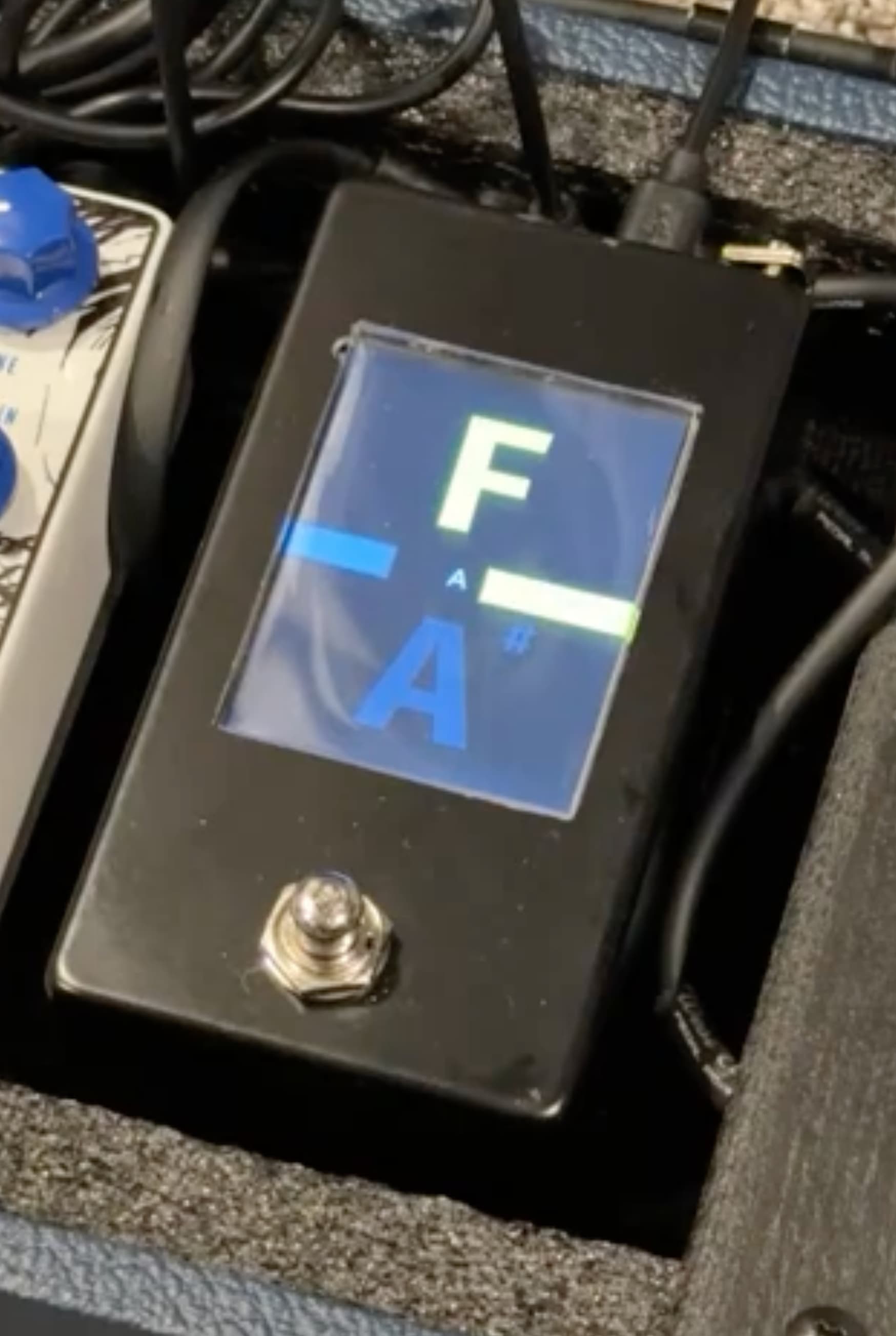
Here’s another with an enclosure we ordered from Tayda as a prototype and I’ve cut a piece of acrylic to be extremely tight against the openings of the enclosure cutout. In this case, the enclosure cutout is too large and you’re seeing the metal borders of the resistive touch panel on the edges (yuck).
The Cheap Yellow Display/CYD (ESP32-2432S028R) is pretty common and easily available and it’s what we started with. Everything was working great with it until we went to make it have a professional mount in a pedal. The CYD’s LCD isn’t strong enough to withstand being mounted without a cover glass. We’ve been experimenting for months trying to find something that’d be acceptable and easily doable by home DIY assemblers.
Some constraints:
We can only cut (order) straight holes cut into the top of an enclosure
We want it to be a relatively inexpensive screen
It needs to be durable
ESP32 (inexpensive)
3 GPIOs available: 1 for momentary foot switch, 1 for controlling the DPDT relay, and 1 ADC for reading the incoming guitar signal
Preferably fits into a 1590B enclosure (which is a little smaller than the 125B)
The Waveshare stuff looked great for nailing a good professional look though I don’t know how well it would have held up on a pedalboard.
Here’s a video (sorry, kind of long) I made of how it’s working with the Expensive Blue Display (EBD4) from Waveshare and it had a lot of promise but I just don’t think it’ll be awesome with the slowness of the display: https://www.youtube.com/live/clqjYM7ioD4
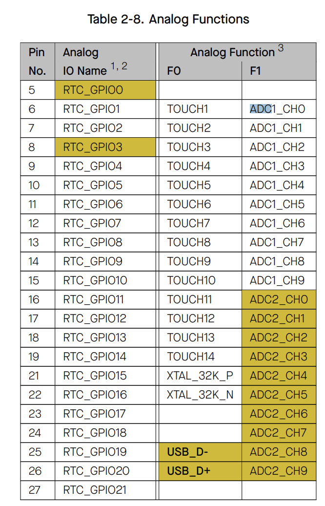
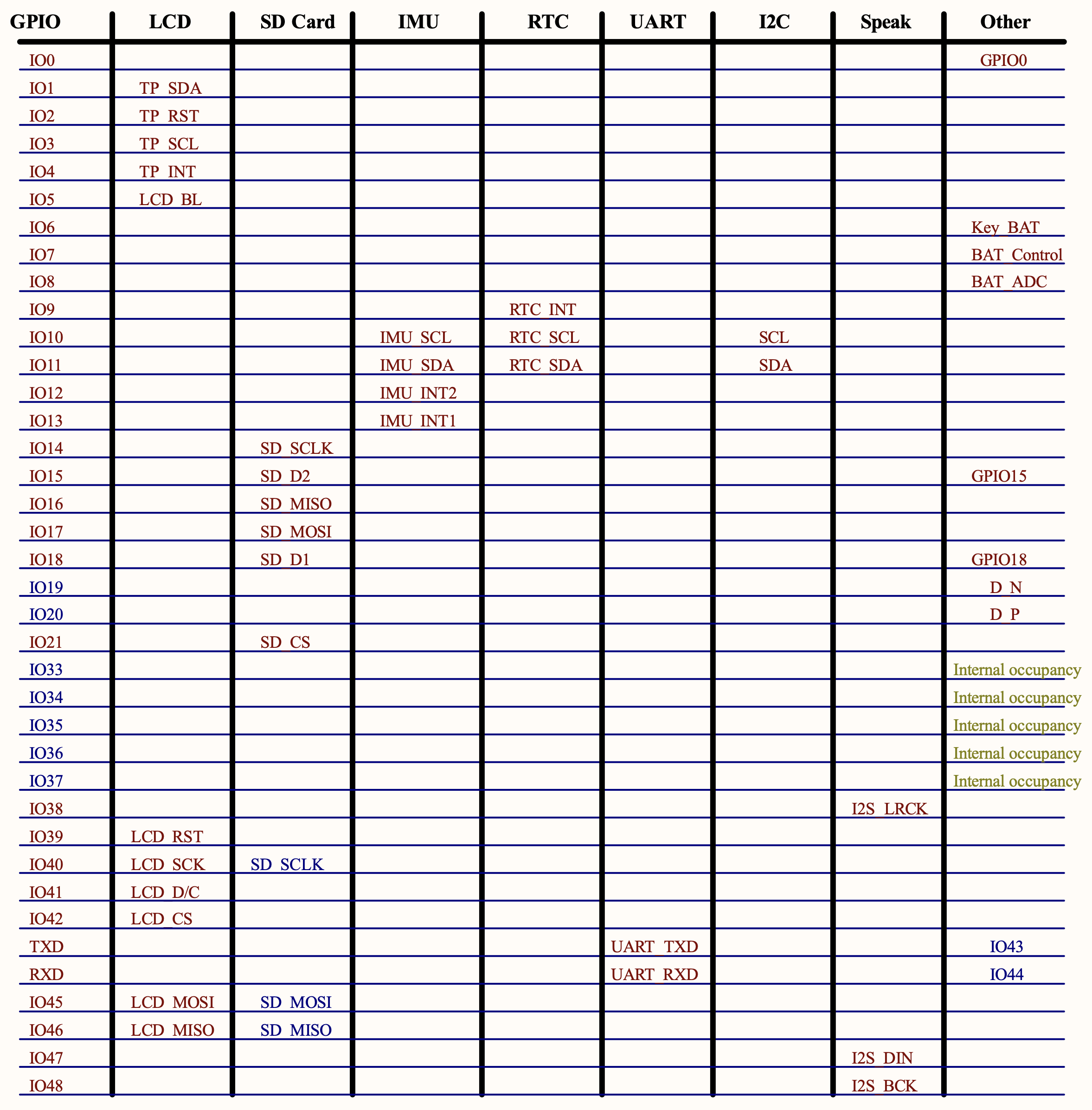
GPIO1-GPIO10 are available for continuous internal ADC reading. The Waveshare EBD2 GPIO10 and GPIO11 pins are SCL and SDA respectively. Those are what I’ve been trying to use for the external ADS1015 ADC chip. However, upon closer inspection of the EBD2’s datasheet, it made me wonder if ADC1_CH9 would actually work as ADC (since I am not using any other I2C device).
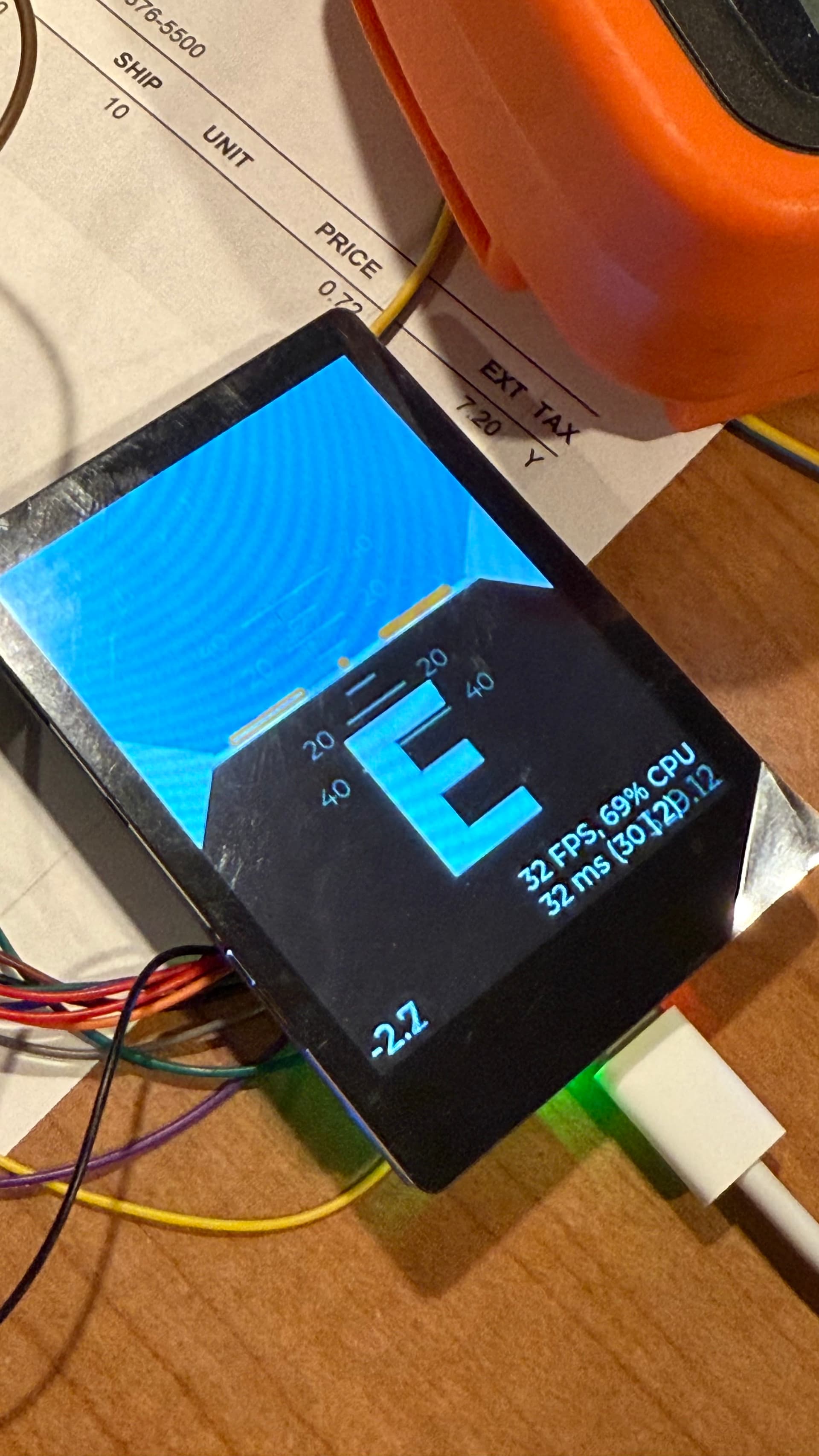
Sadly, the internal ADC in this EBD2 Waveshare seems to be a lot worse quality than the CYD’s ADC. It’s a LOT more jumpy … so much so that the higher strings are struggling to stay stable enough to really tune.