ST7701 with LVGL 9 (Waveshare 2.8” 480x640 ESP32-S3)

So I just tried to get closer to making it work with the libs provided by Espressif. It’s call compiling and the backlight turns on but nothing is getting displayed.

tuner_lcd.h

#if !defined(TUNER_LCD)
#define TUNER_LCD

#include "esp_err.h"
#include "esp_io_expander.h"
#include "esp_lcd_panel_io.h"

#define LCD_IO_SPI_CS_EXPANDER (IO_EXPANDER_PIN_NUM_1)

/********************* LCD *********************/

#define LCD_MOSI 1
#define LCD_SCLK 2
#define LCD_CS  -1      // Using EXIO
// The pixel number in horizontal and vertical
#define LCD_V_RES               640
#define LCD_H_RES               480
#define LCD_DATA_WIDTH          16
#define LCD_BIT_PER_PIXEL       (18)

// #define LCD_BUF_LINES      32
// #define LCD_DRAWBUF_SIZE   (LCD_H_RES * LCD_BUF_LINES) // works with both DMA and SPIRAM but slower in SPIRAM
// #define LCD_DRAWBUF_SIZE   (LCD_H_RES * LCD_V_RES * LCD_DATA_WIDTH / 10) // crashes when using
#define LCD_DRAWBUF_SIZE   (LCD_H_RES * LCD_V_RES / 10) // works in DMA and SPIRAM but slower in SPIRAM by 1-2 fps

#define LCD_PIXEL_CLOCK_HZ     (30 * 1000 * 1000) // original as defined by Waveshare
#define LCD_BK_LIGHT_ON_LEVEL  1
#define LCD_BK_LIGHT_OFF_LEVEL !LCD_BK_LIGHT_ON_LEVEL
#define PIN_NUM_BK_LIGHT       6
#define PIN_NUM_HSYNC          38
#define PIN_NUM_VSYNC          39
#define PIN_NUM_DE             40
#define PIN_NUM_PCLK           41
#define PIN_NUM_DATA0          5  // B0
#define PIN_NUM_DATA1          45 // B1
#define PIN_NUM_DATA2          48 // B2
#define PIN_NUM_DATA3          47 // B3
#define PIN_NUM_DATA4          21 // B4
#define PIN_NUM_DATA5          14 // G0
#define PIN_NUM_DATA6          13 // G1
#define PIN_NUM_DATA7          12 // G2
#define PIN_NUM_DATA8          11 // G3
#define PIN_NUM_DATA9          10 // G4
#define PIN_NUM_DATA10         9  // G5
#define PIN_NUM_DATA11         46 // R0
#define PIN_NUM_DATA12         3  // R1
#define PIN_NUM_DATA13         8  // R2
#define PIN_NUM_DATA14         18 // R3
#define PIN_NUM_DATA15         17 // R4
#define PIN_NUM_DISP_EN        -1

#define LCD_NUM_OF_FRAME_BUFFERS        2

#define LEDC_TIMER              LEDC_TIMER_0
#define LEDC_MODE               LEDC_LOW_SPEED_MODE
#define LEDC_OUTPUT_IO          PIN_NUM_BK_LIGHT      // Define the output GPIO
#define LEDC_CHANNEL            LEDC_CHANNEL_0
#define LEDC_DUTY_RES           LEDC_TIMER_10_BIT // Set duty resolution to 10 bits
#define LEDC_DUTY               (512)    // Set duty to 50%. (2^10) * 50% = 512
#define LEDC_FREQUENCY          (30000) // Frequency in Hertz. Set frequency at 30 kHz to keep it out of the audible range.
#define Backlight_MAX           100

esp_err_t init_tuner_lcd(esp_lcd_panel_io_handle_t *io_handle, esp_lcd_panel_handle_t *panel_handle);
esp_err_t lcd_display_brightness_set(uint8_t brightness);


#endif // TUNER_LCD

tuner_lcd_c

#include "tuner_lcd.h"

// #include "freertos/task.h"
// // #include "soc/soc.h"

#include <driver/gpio.h>
#include <driver/spi_master.h>

#include "esp_system.h"
#include "esp_log.h"
#include "esp_err.h"
#include "esp_check.h"
#include "esp_lcd_panel_vendor.h"
#include "esp_lcd_panel_ops.h"
#include "esp_io_expander_tca9554.h"
#include "esp_lcd_panel_io_additions.h"
#include "esp_lcd_st7701.h"
#include "driver/ledc.h"

static const char *TAG = "LCD";

extern i2c_master_bus_handle_t i2c_bus_handle;

static esp_io_expander_handle_t io_expander;

esp_err_t init_tuner_lcd(esp_lcd_panel_io_handle_t *io_handle, esp_lcd_panel_handle_t *panel_handle) {
    // Create TCA9554 IO Expander
    ESP_ERROR_CHECK(esp_io_expander_new_i2c_tca9554(i2c_bus_handle, ESP_IO_EXPANDER_I2C_TCA9554_ADDRESS_000, &io_expander));

    ESP_LOGI(TAG, "Install 3-wire SPI panel IO");
    spi_line_config_t line_config = {
        .cs_io_type = IO_TYPE_EXPANDER,
        .cs_gpio_num = LCD_IO_SPI_CS_EXPANDER,
        .scl_io_type = IO_TYPE_GPIO,
        .scl_gpio_num = LCD_SCLK,
        .sda_io_type = IO_TYPE_GPIO,
        .sda_gpio_num = LCD_MOSI,
        .io_expander = io_expander,
    };

    esp_lcd_panel_io_3wire_spi_config_t io_config = ST7701_PANEL_IO_3WIRE_SPI_CONFIG(line_config, 0);
    ESP_ERROR_CHECK(esp_lcd_new_panel_io_3wire_spi(&io_config, io_handle));

    ESP_LOGI(TAG, "Install ST7701 panel driver");
    esp_lcd_rgb_panel_config_t rgb_config = {
        .data_width = LCD_DATA_WIDTH,
        .psram_trans_align = 64,
        .num_fbs = LCD_NUM_OF_FRAME_BUFFERS,
        // .bounce_buffer_size_px = 10,
        .clk_src = LCD_CLK_SRC_DEFAULT,
        .disp_gpio_num = PIN_NUM_DISP_EN,
        .pclk_gpio_num = PIN_NUM_PCLK,
        .vsync_gpio_num = PIN_NUM_VSYNC,
        .hsync_gpio_num = PIN_NUM_HSYNC,
        .de_gpio_num = PIN_NUM_DE,
        .data_gpio_nums = {
            PIN_NUM_DATA0,
            PIN_NUM_DATA1,
            PIN_NUM_DATA2,
            PIN_NUM_DATA3,
            PIN_NUM_DATA4,
            PIN_NUM_DATA5,
            PIN_NUM_DATA6,
            PIN_NUM_DATA7,
            PIN_NUM_DATA8,
            PIN_NUM_DATA9,
            PIN_NUM_DATA10,
            PIN_NUM_DATA11,
            PIN_NUM_DATA12,
            PIN_NUM_DATA13,
            PIN_NUM_DATA14,
            PIN_NUM_DATA15,
        },
        .timings = {
            .pclk_hz = LCD_PIXEL_CLOCK_HZ,
            .h_res = LCD_H_RES,
            .v_res = LCD_V_RES, 
            .hsync_back_porch = 10,
            .hsync_front_porch = 50,
            .hsync_pulse_width = 8,
            .vsync_back_porch = 18,
            .vsync_front_porch = 8,
            .vsync_pulse_width = 2,
            .flags.pclk_active_neg = false,
        },
        .flags.fb_in_psram = true, // allocate frame buffer in PSRAM
    };
    st7701_vendor_config_t vendor_config = {
        .rgb_config = &rgb_config,
        .flags.enable_io_multiplex = true, // TODO: not sure what this should be
    };

    const esp_lcd_panel_dev_config_t panel_config = {
        .reset_gpio_num = GPIO_NUM_NC,
        .rgb_ele_order = LCD_RGB_ELEMENT_ORDER_BGR,
        .bits_per_pixel = LCD_BIT_PER_PIXEL,
        .vendor_config = &vendor_config,
    };

    esp_err_t e = esp_lcd_new_panel_st7701(*io_handle, &panel_config, panel_handle);
    ESP_LOGI(TAG, "esp_lcd_new_panel_st7701() returned %s", esp_err_to_name(e));
    e = esp_lcd_panel_reset(*panel_handle);
    ESP_LOGI(TAG, "esp_lcd_panel_reset() returned %s", esp_err_to_name(e));
    e = esp_lcd_panel_init(*panel_handle);
    ESP_LOGI(TAG, "esp_lcd_panel_init() returned %s", esp_err_to_name(e));

/********************* BackLight *********************/
    // Prepare and then apply the LEDC PWM timer configuration
    ledc_timer_config_t ledc_timer = {
        .speed_mode       = LEDC_MODE,
        .timer_num        = LEDC_TIMER,
        .duty_resolution  = LEDC_DUTY_RES,
        .freq_hz          = LEDC_FREQUENCY,  // Set output frequency at 30 kHz
        .clk_cfg          = LEDC_AUTO_CLK
    };
    ESP_ERROR_CHECK(ledc_timer_config(&ledc_timer));

    // Prepare and then apply the LEDC PWM channel configuration
    ledc_channel_config_t ledc_channel = {
        .speed_mode     = LEDC_MODE,
        .channel        = LEDC_CHANNEL,
        .timer_sel      = LEDC_TIMER,
        .intr_type      = LEDC_INTR_DISABLE,
        .gpio_num       = LEDC_OUTPUT_IO,
        .duty           = 0, // Set duty to 0%
        .hpoint         = 0
    };
    ESP_ERROR_CHECK(ledc_channel_config(&ledc_channel));
    lcd_display_brightness_set(100);

    return ESP_OK;
}

esp_err_t lcd_display_brightness_set(uint8_t brightness) {
    if (brightness > Backlight_MAX || brightness < 0) {
      ESP_LOGI(TAG, "Set Backlight parameters in the range of 0 to 100 ");
    } else {
      ESP_ERROR_CHECK(ledc_set_duty(LEDC_MODE, LEDC_CHANNEL, brightness*(1024/100)));    // Set duty
      ESP_ERROR_CHECK(ledc_update_duty(LEDC_MODE, LEDC_CHANNEL));                 // Update duty to apply the new value
    }
  
    return ESP_OK;
}

init code:

static esp_lcd_panel_io_handle_t lcd_io;
static esp_lcd_panel_handle_t lcd_panel;

static void *buf1 = NULL;
static void *buf2 = NULL;

void lvgl_port_flush_cb(lv_display_t *display, const lv_area_t *area, uint8_t *px_map) {
    esp_lcd_panel_draw_bitmap(lcd_panel, area->x1, area->y1, area->x2 + 1, area->y2 + 1, px_map);
    lv_display_flush_ready(display);
}

// NOT USED YET
bool spi_trans_done_cb(esp_lcd_panel_io_handle_t panel_io, esp_lcd_panel_io_event_data_t *edata, void *user_ctx) {
    if (!user_ctx) {
        return false;
    }
    lv_display_flush_ready((lv_display_t *)user_ctx);
    return false; // return true if a higher priority task needs a reschedule
}

static void tick_timer_cb(void *arg)
{
    /* Tell LVGL how many milliseconds has elapsed */
    lv_tick_inc(5);
}

esp_err_t lvgl_init() {
    lv_init();
    const esp_timer_create_args_t tick_timer_args = {
        .callback = &tick_timer_cb,
        .name = "tick_timer"
    };
    esp_timer_handle_t tick_timer = NULL;
    ESP_ERROR_CHECK(esp_timer_create(&tick_timer_args, &tick_timer));
    ESP_ERROR_CHECK(esp_timer_start_periodic(tick_timer, 5 * 1000));  // every 5 milliseconds

    lvgl_display = lv_display_create(LCD_H_RES, LCD_V_RES);
    lv_display_set_flush_cb(lvgl_display, lvgl_port_flush_cb);


    // Allocate and set the display buffers
    buf1 = heap_caps_malloc(LCD_DRAWBUF_SIZE, MALLOC_CAP_SPIRAM);
    assert(buf1);
    buf2 = heap_caps_malloc(LCD_DRAWBUF_SIZE, MALLOC_CAP_SPIRAM);
    assert(buf2);

    lv_display_set_buffers(lvgl_display, buf1, buf2, LCD_DRAWBUF_SIZE, LV_DISPLAY_RENDER_MODE_PARTIAL);

    return ESP_OK;
}

void tuner_gui_task(void *pvParameter) {
    ESP_ERROR_CHECK(init_tuner_lcd(&lcd_io, &lcd_panel));
    ESP_ERROR_CHECK(lvgl_init());

    // Draw initial LVGL objects here
...
        while(1) {
            // draw and manipulate lvgl objects
            lv_timer_handler();
            vTaskDelay(pdMS_TO_TICKS(33));
        }
}
The only warning I get with that code:

W (1629) lcd_panel.io.3wire_spi: Delete but keep CS line inactive

you are not sending any initialization commands to the display.

Those is going to slow things down as well…

Give me me a bit to put together the code for ya to get you started.

OK so something along these lines…

#include "tuner_lcd.h"
#include "lvgl.h"
#include "esp_lcd_panel_rgb.h"
#include "esp_lcd_panel_interface.h"
#include "esp_lcd_panel_io.h"


lv_display_t *display = NULL;


bool rgb_bus_trans_done_cb(esp_lcd_panel_handle_t panel,
                                    const esp_lcd_rgb_panel_event_data_t *edata, void *user_ctx)
    {
        LCD_UNUSED(edata);
        rgb_panel_t *rgb_panel = __containerof(panel, rgb_panel_t, base);
        uint8_t *curr_buf = rgb_panel->fbs[rgb_panel->cur_fb_index];

        if (curr_buf != active_fb) {
            active_fb = curr_buf;
            lv_display_flush_ready((lv_display_t *)user_ctx);
        }

        return false;
    }


void lvgl_port_flush_cb(lv_display_t *display, const lv_area_t *area, uint8_t *px_map) {
    esp_lcd_panel_draw_bitmap(lcd_panel, area->x1, area->y1, area->x2 + 1, area->y2 + 1, px_map);
}


static void tick_timer_cb(void *arg)
{
    /* Tell LVGL how many milliseconds has elapsed */
    lv_tick_inc(5);
}


esp_err_t lvgl_init()
{
    lv_init();
    display = lv_display_create(LCD_H_RES, LCD_V_RES);

    esp_timer_create_args_t tick_timer_args = {
        .callback = &tick_timer_cb,
        .name = "tick_timer"
    };
    esp_timer_handle_t tick_timer = NULL;
    ESP_ERROR_CHECK(esp_timer_create(&tick_timer_args, &tick_timer));
    ESP_ERROR_CHECK(esp_timer_start_periodic(tick_timer, 5 * 1000));  // every 5 milliseconds


    lv_display_set_flush_cb(lvgl_display, lvgl_port_flush_cb);


    lv_display_set_buffers(lvgl_display, buf1, buf2, LCD_DRAWBUF_SIZE, LV_DISPLAY_RENDER_MODE_DIRECT);

    return ESP_OK;
}

void tuner_gui_task(void *pvParameter) {
    ESP_ERROR_CHECK(init_tuner_lcd(&lcd_io, &lcd_panel));
    ESP_ERROR_CHECK(lvgl_init());

    // Draw initial LVGL objects here
    while(1) {
        // draw and manipulate lvgl objects
        lv_timer_handler();
        vTaskDelay(pdMS_TO_TICKS(5));
    }
}
#if !defined(TUNER_LCD)
#define TUNER_LCD

#include "esp_err.h"
#include "driver/i2c_master.h"

#include "hal/lcd_hal.h"
#include "esp_pm.h"
#include "esp_intr_alloc.h"
#include "esp_heap_caps.h"

#include "esp_io_expander.h

#include "esp_lcd_panel_io.h"
#include "esp_lcd_panel_ops.h"
#include "esp_lcd_panel_interface.h"
#include "esp_lcd_panel_rgb.h"

#include "lvgl.h"


#define I2C_SDA  ?
#define I2C_SCL  ?


#define LCD_IO_SPI_CS_EXPANDER (IO_EXPANDER_PIN_NUM_1)

/********************* LCD *********************/

#define LCD_MOSI 1
#define LCD_SCLK 2
#define LCD_CS  -1      // Using EXIO
// The pixel number in horizontal and vertical
#define LCD_V_RES               640
#define LCD_H_RES               480
#define LCD_DATA_WIDTH          16
#define LCD_BIT_PER_PIXEL       (16)

// #define LCD_BUF_LINES      32
// #define LCD_DRAWBUF_SIZE   (LCD_H_RES * LCD_BUF_LINES) // works with both DMA and SPIRAM but slower in SPIRAM
// #define LCD_DRAWBUF_SIZE   (LCD_H_RES * LCD_V_RES * LCD_DATA_WIDTH / 10) // crashes when using
#define LCD_FRAMEBUF_SIZE   (LCD_H_RES * LCD_V_RES * 2) // works in DMA and SPIRAM but slower in SPIRAM by 1-2 fps

#define LCD_PIXEL_CLOCK_HZ     (30 * 1000 * 1000) // original as defined by Waveshare
#define LCD_BK_LIGHT_ON_LEVEL  1
#define LCD_BK_LIGHT_OFF_LEVEL !LCD_BK_LIGHT_ON_LEVEL
#define PIN_NUM_BK_LIGHT       6
#define PIN_NUM_HSYNC          38
#define PIN_NUM_VSYNC          39
#define PIN_NUM_DE             40
#define PIN_NUM_PCLK           41
#define PIN_NUM_DATA0          5  // B0
#define PIN_NUM_DATA1          45 // B1
#define PIN_NUM_DATA2          48 // B2
#define PIN_NUM_DATA3          47 // B3
#define PIN_NUM_DATA4          21 // B4
#define PIN_NUM_DATA5          14 // G0
#define PIN_NUM_DATA6          13 // G1
#define PIN_NUM_DATA7          12 // G2
#define PIN_NUM_DATA8          11 // G3
#define PIN_NUM_DATA9          10 // G4
#define PIN_NUM_DATA10         9  // G5
#define PIN_NUM_DATA11         46 // R0
#define PIN_NUM_DATA12         3  // R1
#define PIN_NUM_DATA13         8  // R2
#define PIN_NUM_DATA14         18 // R3
#define PIN_NUM_DATA15         17 // R4
#define PIN_NUM_DISP_EN        -1

#define LEDC_TIMER              LEDC_TIMER_0
#define LEDC_MODE               LEDC_LOW_SPEED_MODE
#define LEDC_OUTPUT_IO          PIN_NUM_BK_LIGHT      // Define the output GPIO
#define LEDC_CHANNEL            LEDC_CHANNEL_0
#define LEDC_DUTY_RES           LEDC_TIMER_10_BIT // Set duty resolution to 10 bits
#define LEDC_DUTY               (512)    // Set duty to 50%. (2^10) * 50% = 512
#define LEDC_FREQUENCY          (30000) // Frequency in Hertz. Set frequency at 30 kHz to keep it out of the audible range.
#define Backlight_MAX           100

esp_err_t init_tuner_lcd(esp_lcd_panel_io_handle_t *io_handle, esp_lcd_panel_handle_t *panel_handle);
esp_err_t lcd_display_brightness_set(uint8_t brightness);


extern i2c_master_bus_handle_t i2c_bus_handle;
extern esp_lcd_panel_io_handle_t spi3wire_io_handle;
extern esp_io_expander_handle_t io_expander;


extern void *buf1;
extern void *buf2;
extern void *active_buf;
extern lv_display_t *display;

bool rgb_bus_trans_done_cb(esp_lcd_panel_handle_t panel,
                                    const esp_lcd_rgb_panel_event_data_t *edata, void *user_ctx);


typedef struct {
    esp_lcd_panel_t base;  // Base class of generic lcd panel
    int panel_id;          // LCD panel ID
    lcd_hal_context_t hal; // Hal layer object
    size_t data_width;     // Number of data lines
    size_t fb_bits_per_pixel; // Frame buffer color depth, in bpp
    size_t num_fbs;           // Number of frame buffers
    size_t output_bits_per_pixel; // Color depth seen from the output data line. Default to fb_bits_per_pixel, but can be changed by YUV-RGB conversion
    size_t sram_trans_align;  // Alignment for framebuffer that allocated in SRAM
    size_t psram_trans_align; // Alignment for framebuffer that allocated in PSRAM
    int disp_gpio_num;     // Display control GPIO, which is used to perform action like "disp_off"
    intr_handle_t intr;    // LCD peripheral interrupt handle
    esp_pm_lock_handle_t pm_lock; // Power management lock
    size_t num_dma_nodes;  // Number of DMA descriptors that used to carry the frame buffer
    uint8_t *fbs[3]; // Frame buffers
    uint8_t cur_fb_index;  // Current frame buffer index
    uint8_t bb_fb_index;  // Current frame buffer index which used by bounce buffer
} rgb_panel_t;


#endif // TUNER_LCD
#include "tuner_lcd.h"

// #include "freertos/task.h"
// // #include "soc/soc.h"

#include <stdint.h>

#include "driver/gpio.h"
#include "driver/spi_master.h"

#include "esp_system.h"
#include "esp_log.h"
#include "esp_err.h"
#include "esp_check.h"
#include "driver/ledc.h"
#include "esp_err.h"
#include "driver/i2c_master.h"

#include "esp_lcd_panel_vendor.h"
#include "esp_lcd_panel_ops.h"
#include "esp_lcd_panel_io_additions.h"
#include "esp_lcd_st7701.h"
#include "esp_io_expander.h"
#include "esp_io_expander_tca9554.h"
#include "esp_lcd_panel_rgb.h"


static const char *TAG = "LCD";


i2c_master_bus_handle_t i2c_bus_handle = NULL;
esp_lcd_panel_io_handle_t spi3wire_io_handle = NULL;
esp_io_expander_handle_t io_expander = NULL;

void *buf1 = NULL;
void *buf2 = NULL;
void *active_buf = NULL;


const st7701_lcd_init_cmd_t init_cmds[] = {
    { 0xFF, (uint8_t []){0x77, 0x01, 0x00, 0x00, 0x13}, 5, 0 },
    { 0xEF, (uint8_t []){0x08}, 1, 0 },
    { 0xFF, (uint8_t []){0x77, 0x01, 0x00, 0x00, 0x10}, 5, 0 },
    { 0xC0, (uint8_t []){0x4F, 0x00}, 2, 0 },
    { 0xC1, (uint8_t []){0x10, 0x02}, 2, 0 },
    { 0xC2, (uint8_t []){0x07, 0x02}, 2, 0 },
    { 0xCC, (uint8_t []){0x10}, 1, 0 },
    { 0xB0, (uint8_t []){0x00, 0x10, 0x17, 0x0D, 0x11, 0x06, 0x05, 0x08, 0x07, 0x1F, 0x04, 0x11, 0x0E, 0x29, 0x30, 0x1F}, 16, 0 },
    { 0xB1, (uint8_t []){0x00, 0x0D, 0x14, 0x0E, 0x11, 0x06, 0x04, 0x08, 0x08, 0x20, 0x05, 0x13, 0x13, 0x26, 0x30, 0x1F}, 16, 0 },
    { 0xFF, (uint8_t []){0x77, 0x01, 0x00, 0x00, 0x11}, 5, 0 },
    { 0xB0, (uint8_t []){0x65}, 1, 0 },
    { 0xB1, (uint8_t []){0x71}, 1, 0 },
    { 0xB2, (uint8_t []){0x82}, 1, 0 },
    { 0xB3, (uint8_t []){0x80}, 1, 0 },
    { 0xB5, (uint8_t []){0x42}, 1, 0 },
    { 0xB7, (uint8_t []){0x85}, 1, 0 },
    { 0xB8, (uint8_t []){0x20}, 1, 0 },
    { 0xC0, (uint8_t []){0x09}, 1, 0 },
    { 0xC1, (uint8_t []){0x78}, 1, 0 },
    { 0xC2, (uint8_t []){0x78}, 1, 0 },
    { 0xD0, (uint8_t []){0x88}, 1, 0 },
    { 0xEE, (uint8_t []){0x42}, 1, 0 },
    { 0xE0, (uint8_t []){0x00, 0x00, 0x02}, 3, 0 },
    { 0xE1, (uint8_t []){0x04, 0xA0, 0x06, 0xA0, 0x05, 0xA0, 0x07, 0xA0, 0x00, 0x44, 0x44}, 11, 0 },
    { 0xE2, (uint8_t []){0x00, 0x00, 0x00, 0x00, 0x00, 0x00, 0x00, 0x00, 0x00, 0x00, 0x00, 0x00}, 12, 0 },
    { 0xE3, (uint8_t []){0x00, 0x00, 0x22, 0x22}, 4, 0 },
    { 0xE4, (uint8_t []){0x44, 0x44}, 2, 0 },
    { 0xE5, (uint8_t []){0x0c, 0x90, 0xA0, 0xA0, 0x0E, 0x92, 0xA0, 0xA0, 0x08, 0x8C, 0xA0, 0xA0, 0x0A, 0x8E, 0xA0, 0xA0}, 16, 0 },
    { 0xE6, (uint8_t []){0x00, 0x00, 0x22, 0x22}, 4, 0 },
    { 0xE7, (uint8_t []){0x44, 0x44}, 2, 0 },
    { 0xE8, (uint8_t []){0x0D, 0x91, 0xA0, 0xA0, 0x0F, 0x93, 0xA0, 0xA0, 0x09, 0x8D, 0xA0, 0xA0, 0x0B, 0x8F, 0xA0, 0xA0}, 16, 0 },
    { 0xEB, (uint8_t []){0x00, 0x00, 0xE4, 0xE4, 0x44, 0x00, 0x40}, 7, 0 },
    { 0xED, (uint8_t []){0xFF, 0xF5, 0x47, 0x6F, 0x0B, 0xA1, 0xAB, 0xFF, 0xFF, 0xBA, 0x1A, 0xB0, 0xF6, 0x74, 0x5F, 0xFF}, 16, 0 },
    { 0xEF, (uint8_t []){0x08, 0x08, 0x08, 0x40, 0x3F, 0x64}, 6, 0 },
    { 0xFF, (uint8_t []){0x77, 0x01, 0x00, 0x00, 0x00}, 5, 0 },
    { 0xFF, (uint8_t []){0x77, 0x01, 0x00, 0x00, 0x13}, 5, 0 },
    { 0xE6, (uint8_t []){0x16, 0x7C}, 2, 0 },
    { 0xE8, (uint8_t []){0x00, 0x0E}, 2, 0 },
    { 0xFF, (uint8_t []){0x77, 0x01, 0x00, 0x00, 0x00}, 5, 0 },
    { 0x11, (uint8_t []){0x00}, 1, 200 },
    { 0xFF, (uint8_t []){0x77, 0x01, 0x00, 0x00, 0x13}, 5, 0 },
    { 0xE8, (uint8_t []){0x00,  0x0C}, 2, 150 },
    { 0xE8, (uint8_t []){0x00,  0x00}, 2, 0 },
    { 0xFF, (uint8_t []){0x77, 0x01, 0x00, 0x00, 0x00}, 5, 0 },
    { 0x29, (uint8_t []){0x00}, 1, 0 },
    { 0x35, (uint8_t []){0x00}, 1, 0 },
    { 0x11, (uint8_t []){0x00}, 1, 200 },
    { 0x29, (uint8_t []){0x00}, 1, 100 }
}


esp_err_t init_tuner_lcd(esp_lcd_panel_io_handle_t *io_handle, esp_lcd_panel_handle_t *panel_handle)
{
    i2c_master_bus_config_t bus_config = {
        .i2c_port = 0,
        .sda_io_num = I2C_SDA,
        .scl_io_num = I2C_SCL,
        .clk_source = I2C_CLK_SRC_DEFAULT,
    };
    i2c_new_master_bus(&bus_config, &i2c_bus_handle);

    // Create TCA9554 IO Expander
    ESP_ERROR_CHECK(esp_io_expander_new_i2c_tca9554(i2c_bus_handle, ESP_IO_EXPANDER_I2C_TCA9554_ADDRESS_000, &io_expander));

    ESP_LOGI(TAG, "Install 3-wire SPI panel IO");

    esp_lcd_panel_io_3wire_spi_config_t spi3wire_config = {
        .flags = {
            .use_dc_bit = 1,
            .dc_zero_on_data = 0,
            .lsb_first = 0,
            .cs_high_active = 0,
            .del_keep_cs_inactive = 0,
        },
        .spi_mode = 0;
        .expect_clk_speed = 4000000;
        .cs_io_type = IO_TYPE_EXPANDER,
        .cs_gpio_num = LCD_IO_SPI_CS_EXPANDER,
        .scl_io_type = IO_TYPE_GPIO,
        .scl_gpio_num = LCD_SCLK,
        .sda_io_type = IO_TYPE_GPIO,
        .sda_gpio_num = LCD_MOSI,
        .io_expander = &io_expander
    };


    ESP_ERROR_CHECK(esp_lcd_new_panel_io_3wire_spi(&spi3wire_config, &spi3wire_io_handle));

    ESP_LOGI(TAG, "Install ST7701 panel driver");
    esp_lcd_rgb_panel_config_t rgb_config = {
        .data_width = LCD_DATA_WIDTH,
        .psram_trans_align = 64,
        .num_fbs = 2,
        .bits_per_pixel = 16,
        .clk_src = LCD_CLK_SRC_DEFAULT,
        .disp_gpio_num = PIN_NUM_DISP_EN,
        .pclk_gpio_num = PIN_NUM_PCLK,
        .vsync_gpio_num = PIN_NUM_VSYNC,
        .hsync_gpio_num = PIN_NUM_HSYNC,
        .de_gpio_num = PIN_NUM_DE,
        .data_gpio_nums = {
            PIN_NUM_DATA0,
            PIN_NUM_DATA1,
            PIN_NUM_DATA2,
            PIN_NUM_DATA3,
            PIN_NUM_DATA4,
            PIN_NUM_DATA5,
            PIN_NUM_DATA6,
            PIN_NUM_DATA7,
            PIN_NUM_DATA8,
            PIN_NUM_DATA9,
            PIN_NUM_DATA10,
            PIN_NUM_DATA11,
            PIN_NUM_DATA12,
            PIN_NUM_DATA13,
            PIN_NUM_DATA14,
            PIN_NUM_DATA15,
        },
        .timings = {
            .pclk_hz = LCD_PIXEL_CLOCK_HZ,
            .h_res = LCD_H_RES,
            .v_res = LCD_V_RES,
            .hsync_back_porch = 10,
            .hsync_front_porch = 50,
            .hsync_pulse_width = 8,
            .vsync_back_porch = 18,
            .vsync_front_porch = 8,
            .vsync_pulse_width = 2,
            .flags.pclk_active_neg = false,
        },
        .flags.fb_in_psram = true, // allocate frame buffer in PSRAM
    };

    st7701_vendor_config_t vendor_config = {
        .init_cmds = init_cmds,
        .init_cmds_size = 48,
        .rgb_config = &rgb_config,
        .flags = {
            .mirror_by_cmd = 1,
            .enable_io_multiplex = false
        }
    };

    const esp_lcd_panel_dev_config_t panel_config = {
        .reset_gpio_num = GPIO_NUM_NC,
        .rgb_ele_order = LCD_RGB_ELEMENT_ORDER_RGB,
        .bits_per_pixel = LCD_BIT_PER_PIXEL,
        .vendor_config = &vendor_config,
    };

    esp_err_t e = esp_lcd_new_panel_st7701(spi3wire_io_handle, &panel_config, &panel_handle);


    rgb_panel_t *rgb_panel = __containerof(panel_handle, rgb_panel_t, base);
    buf1 = rgb_panel->fbs[0];
    buf2 = rgb_panel->fbs[1];
    active_buf = buf2;  // this is not really the active buffer

    esp_lcd_rgb_panel_event_callbacks_t callbacks = { .on_vsync = rgb_bus_trans_done_cb };
    esp_lcd_rgb_panel_register_event_callbacks(panel_handle, &callbacks, display);

    ESP_LOGI(TAG, "esp_lcd_new_panel_st7701() returned %s", esp_err_to_name(e));
    e = esp_lcd_panel_reset(panel_handle);
    ESP_LOGI(TAG, "esp_lcd_panel_reset() returned %s", esp_err_to_name(e));
    e = esp_lcd_panel_init(panel_handle);
    ESP_LOGI(TAG, "esp_lcd_panel_init() returned %s", esp_err_to_name(e));

/********************* BackLight *********************/
    // Prepare and then apply the LEDC PWM timer configuration
    ledc_timer_config_t ledc_timer = {
        .speed_mode       = LEDC_MODE,
        .timer_num        = LEDC_TIMER,
        .duty_resolution  = LEDC_DUTY_RES,
        .freq_hz          = LEDC_FREQUENCY,  // Set output frequency at 30 kHz
        .clk_cfg          = LEDC_AUTO_CLK
    };
    ESP_ERROR_CHECK(ledc_timer_config(&ledc_timer));

    // Prepare and then apply the LEDC PWM channel configuration
    ledc_channel_config_t ledc_channel = {
        .speed_mode     = LEDC_MODE,
        .channel        = LEDC_CHANNEL,
        .timer_sel      = LEDC_TIMER,
        .intr_type      = LEDC_INTR_DISABLE,
        .gpio_num       = LEDC_OUTPUT_IO,
        .duty           = 0, // Set duty to 0%
        .hpoint         = 0
    };
    ESP_ERROR_CHECK(ledc_channel_config(&ledc_channel));
    lcd_display_brightness_set(100);

    return ESP_OK;
}

esp_err_t lcd_display_brightness_set(uint8_t brightness) {
    if (brightness > Backlight_MAX || brightness < 0) {
        ESP_LOGI(TAG, "Set Backlight parameters in the range of 0 to 100 ");
    } else {
        ESP_ERROR_CHECK(ledc_set_duty(LEDC_MODE, LEDC_CHANNEL, brightness*(1024/100)));    // Set duty
        ESP_ERROR_CHECK(ledc_update_duty(LEDC_MODE, LEDC_CHANNEL));                 // Update duty to apply the new value
    }

    return ESP_OK;
}

There are bound to be typos, forgotten puncuation and stuff like that.

Very interesting. I’m trying to get it to work but …

esp_rgb_panel_t is in the esp_lcd_panel_rgb.c file and not exposed through any header files. Should I be making a hack to make that accessible?

Here’s how I currently have it. If I try the direct mode, the OS kills it with a watchdog on the lv_timer_handler() call when I have it using the direct mode. If I lower the buffer size and use partial it doesn’t get killed but nothing appears on the screen either, even when I try loading my own UI and not the “Hello world” label.

void tuner_gui_task(void *pvParameter) {
    ESP_ERROR_CHECK(init_tuner_lcd());
    ESP_ERROR_CHECK(lvgl_init());
    ESP_ERROR_CHECK(app_lvgl_main());

    is_gui_loaded = true; // Prevents some other threads that rely on LVGL from running until the UI is loaded

    lv_obj_t *label = lv_label_create(lv_screen_active());
    lv_label_set_text(label, "Hello world!");
    lv_obj_align(label, LV_ALIGN_CENTER, 0, 0);

    while (1) {
        lv_timer_handler();
        vTaskDelay(pdMS_TO_TICKS(33));
    }
}

tuner_lcd.h

#if !defined(TUNER_LCD)
#define TUNER_LCD

#include "esp_err.h"
#include "esp_io_expander.h"
#include "esp_lcd_panel_io.h"
#include "esp_lcd_panel_rgb.h"
#include "lvgl.h"

#define LCD_IO_SPI_CS_EXPANDER (IO_EXPANDER_PIN_NUM_1)

/********************* LCD *********************/

#define LCD_MOSI 1
#define LCD_SCLK 2
#define LCD_CS  -1      // Using EXIO
// The pixel number in horizontal and vertical
#define LCD_V_RES               640
#define LCD_H_RES               480
#define LCD_DATA_WIDTH          16
// #define LCD_BIT_PER_PIXEL       (18)
#define LCD_BIT_PER_PIXEL       (16)

// #define LCD_BUF_LINES      32
// #define LCD_DRAWBUF_SIZE   (LCD_H_RES * LCD_BUF_LINES) // works with both DMA and SPIRAM but slower in SPIRAM
// #define LCD_DRAWBUF_SIZE   (LCD_H_RES * LCD_V_RES * LCD_DATA_WIDTH / 10) // crashes when using
#define LCD_DRAWBUF_SIZE   (LCD_H_RES * LCD_V_RES / 10) // works in DMA and SPIRAM but slower in SPIRAM by 1-2 fps
// #define LCD_DRAWBUF_SIZE        (LCD_H_RES * LCD_V_RES * 2)

#define LCD_PIXEL_CLOCK_HZ     (30 * 1000 * 1000) // original as defined by Waveshare
#define LCD_BK_LIGHT_ON_LEVEL  1
#define LCD_BK_LIGHT_OFF_LEVEL !LCD_BK_LIGHT_ON_LEVEL
#define PIN_NUM_BK_LIGHT       6
#define PIN_NUM_HSYNC          38
#define PIN_NUM_VSYNC          39
#define PIN_NUM_DE             40
#define PIN_NUM_PCLK           41
#define PIN_NUM_DATA0          5  // B0
#define PIN_NUM_DATA1          45 // B1
#define PIN_NUM_DATA2          48 // B2
#define PIN_NUM_DATA3          47 // B3
#define PIN_NUM_DATA4          21 // B4
#define PIN_NUM_DATA5          14 // G0
#define PIN_NUM_DATA6          13 // G1
#define PIN_NUM_DATA7          12 // G2
#define PIN_NUM_DATA8          11 // G3
#define PIN_NUM_DATA9          10 // G4
#define PIN_NUM_DATA10         9  // G5
#define PIN_NUM_DATA11         46 // R0
#define PIN_NUM_DATA12         3  // R1
#define PIN_NUM_DATA13         8  // R2
#define PIN_NUM_DATA14         18 // R3
#define PIN_NUM_DATA15         17 // R4
#define PIN_NUM_DISP_EN        -1

#define LCD_NUM_OF_FRAME_BUFFERS        2

#define LEDC_TIMER              LEDC_TIMER_0
#define LEDC_MODE               LEDC_LOW_SPEED_MODE
#define LEDC_OUTPUT_IO          PIN_NUM_BK_LIGHT      // Define the output GPIO
#define LEDC_CHANNEL            LEDC_CHANNEL_0
#define LEDC_DUTY_RES           LEDC_TIMER_10_BIT // Set duty resolution to 10 bits
#define LEDC_DUTY               (512)    // Set duty to 50%. (2^10) * 50% = 512
#define LEDC_FREQUENCY          (30000) // Frequency in Hertz. Set frequency at 30 kHz to keep it out of the audible range.
#define Backlight_MAX           100

esp_err_t init_tuner_lcd();
esp_err_t lcd_display_brightness_set(uint8_t brightness);
esp_err_t lvgl_init();

#endif // TUNER_LCD

tuner_lcd.c

#include "tuner_lcd.h"

#include <driver/gpio.h>
#include <driver/spi_master.h>

#include "esp_system.h"
#include "esp_log.h"
#include "esp_err.h"
#include "esp_check.h"
#include "esp_timer.h"
#include "esp_lcd_panel_vendor.h"
#include "esp_lcd_panel_ops.h"
#include "esp_io_expander_tca9554.h"
#include "esp_lcd_panel_io_additions.h"
#include "esp_lcd_st7701.h"
#include "driver/ledc.h"
#include "TCA9554PWR.h"

static const char *TAG = "LCD";

extern i2c_master_bus_handle_t i2c_bus_handle;

static esp_io_expander_handle_t io_expander;
static spi_device_handle_t spi_device;
static esp_lcd_panel_io_handle_t io_handle;
static esp_lcd_panel_handle_t panel_handle;

static void *buf1 = NULL;
static void *buf2 = NULL;
static void *active_buf = NULL;

lv_display_t *lvgl_display = NULL;

void lvgl_port_flush_cb(lv_display_t *display, const lv_area_t *area, uint8_t *px_map);
bool rgb_bus_trans_done_cb(esp_lcd_panel_handle_t panel, const esp_lcd_rgb_panel_event_data_t *edata, void *user_ctx);
static void tick_timer_cb(void *arg);

const st7701_lcd_init_cmd_t init_cmds[] = {
    { 0xFF, (uint8_t []){0x77, 0x01, 0x00, 0x00, 0x13}, 5, 0 },
    { 0xEF, (uint8_t []){0x08}, 1, 0 },
    { 0xFF, (uint8_t []){0x77, 0x01, 0x00, 0x00, 0x10}, 5, 0 },
    { 0xC0, (uint8_t []){0x4F, 0x00}, 2, 0 },
    { 0xC1, (uint8_t []){0x10, 0x02}, 2, 0 },
    { 0xC2, (uint8_t []){0x07, 0x02}, 2, 0 },
    { 0xCC, (uint8_t []){0x10}, 1, 0 },
    { 0xB0, (uint8_t []){0x00, 0x10, 0x17, 0x0D, 0x11, 0x06, 0x05, 0x08, 0x07, 0x1F, 0x04, 0x11, 0x0E, 0x29, 0x30, 0x1F}, 16, 0 },
    { 0xB1, (uint8_t []){0x00, 0x0D, 0x14, 0x0E, 0x11, 0x06, 0x04, 0x08, 0x08, 0x20, 0x05, 0x13, 0x13, 0x26, 0x30, 0x1F}, 16, 0 },
    { 0xFF, (uint8_t []){0x77, 0x01, 0x00, 0x00, 0x11}, 5, 0 },
    { 0xB0, (uint8_t []){0x65}, 1, 0 },
    { 0xB1, (uint8_t []){0x71}, 1, 0 },
    { 0xB2, (uint8_t []){0x82}, 1, 0 },
    { 0xB3, (uint8_t []){0x80}, 1, 0 },
    { 0xB5, (uint8_t []){0x42}, 1, 0 },
    { 0xB7, (uint8_t []){0x85}, 1, 0 },
    { 0xB8, (uint8_t []){0x20}, 1, 0 },
    { 0xC0, (uint8_t []){0x09}, 1, 0 },
    { 0xC1, (uint8_t []){0x78}, 1, 0 },
    { 0xC2, (uint8_t []){0x78}, 1, 0 },
    { 0xD0, (uint8_t []){0x88}, 1, 0 },
    { 0xEE, (uint8_t []){0x42}, 1, 0 },
    { 0xE0, (uint8_t []){0x00, 0x00, 0x02}, 3, 0 },
    { 0xE1, (uint8_t []){0x04, 0xA0, 0x06, 0xA0, 0x05, 0xA0, 0x07, 0xA0, 0x00, 0x44, 0x44}, 11, 0 },
    { 0xE2, (uint8_t []){0x00, 0x00, 0x00, 0x00, 0x00, 0x00, 0x00, 0x00, 0x00, 0x00, 0x00, 0x00}, 12, 0 },
    { 0xE3, (uint8_t []){0x00, 0x00, 0x22, 0x22}, 4, 0 },
    { 0xE4, (uint8_t []){0x44, 0x44}, 2, 0 },
    { 0xE5, (uint8_t []){0x0c, 0x90, 0xA0, 0xA0, 0x0E, 0x92, 0xA0, 0xA0, 0x08, 0x8C, 0xA0, 0xA0, 0x0A, 0x8E, 0xA0, 0xA0}, 16, 0 },
    { 0xE6, (uint8_t []){0x00, 0x00, 0x22, 0x22}, 4, 0 },
    { 0xE7, (uint8_t []){0x44, 0x44}, 2, 0 },
    { 0xE8, (uint8_t []){0x0D, 0x91, 0xA0, 0xA0, 0x0F, 0x93, 0xA0, 0xA0, 0x09, 0x8D, 0xA0, 0xA0, 0x0B, 0x8F, 0xA0, 0xA0}, 16, 0 },
    { 0xEB, (uint8_t []){0x00, 0x00, 0xE4, 0xE4, 0x44, 0x00, 0x40}, 7, 0 },
    { 0xED, (uint8_t []){0xFF, 0xF5, 0x47, 0x6F, 0x0B, 0xA1, 0xAB, 0xFF, 0xFF, 0xBA, 0x1A, 0xB0, 0xF6, 0x74, 0x5F, 0xFF}, 16, 0 },
    { 0xEF, (uint8_t []){0x08, 0x08, 0x08, 0x40, 0x3F, 0x64}, 6, 0 },
    { 0xFF, (uint8_t []){0x77, 0x01, 0x00, 0x00, 0x00}, 5, 0 },
    { 0xFF, (uint8_t []){0x77, 0x01, 0x00, 0x00, 0x13}, 5, 0 },
    { 0xE6, (uint8_t []){0x16, 0x7C}, 2, 0 },
    { 0xE8, (uint8_t []){0x00, 0x0E}, 2, 0 },
    { 0xFF, (uint8_t []){0x77, 0x01, 0x00, 0x00, 0x00}, 5, 0 },
    { 0x11, (uint8_t []){0x00}, 1, 200 },
    { 0xFF, (uint8_t []){0x77, 0x01, 0x00, 0x00, 0x13}, 5, 0 },
    { 0xE8, (uint8_t []){0x00,  0x0C}, 2, 150 },
    { 0xE8, (uint8_t []){0x00,  0x00}, 2, 0 },
    { 0xFF, (uint8_t []){0x77, 0x01, 0x00, 0x00, 0x00}, 5, 0 },
    { 0x29, (uint8_t []){0x00}, 1, 0 },
    { 0x35, (uint8_t []){0x00}, 1, 0 },
    { 0x11, (uint8_t []){0x00}, 1, 200 },
    { 0x29, (uint8_t []){0x00}, 1, 100 }
};

esp_err_t ST7701S_reset(void)
{
    Set_EXIO(TCA9554_EXIO1,false);
    vTaskDelay(pdMS_TO_TICKS(10));
    Set_EXIO(TCA9554_EXIO1,true);
    vTaskDelay(pdMS_TO_TICKS(10));
    return ESP_OK;
}

esp_err_t ST7701S_CS_EN(void)
{
    Set_EXIO(TCA9554_EXIO3,false);
    vTaskDelay(pdMS_TO_TICKS(10));
    return ESP_OK;
}
esp_err_t ST7701S_CS_Dis(void)
{
    Set_EXIO(TCA9554_EXIO3,true);
    vTaskDelay(pdMS_TO_TICKS(10));
    return ESP_OK;
}

esp_err_t init_tuner_lcd() {
    ST7701S_reset();
    ST7701S_CS_EN();
    vTaskDelay(pdMS_TO_TICKS(100));

    const spi_bus_config_t buscfg = { 
        .mosi_io_num = LCD_MOSI,
        .miso_io_num = -1,
        .sclk_io_num = LCD_SCLK,
        .quadhd_io_num = GPIO_NUM_NC,
        .quadwp_io_num = GPIO_NUM_NC,
        .max_transfer_sz = LCD_DRAWBUF_SIZE,
    };

    ESP_RETURN_ON_ERROR(spi_bus_initialize(SPI2_HOST, &buscfg, SPI_DMA_CH_AUTO), TAG, "SPI init failed");

    spi_device_interface_config_t dev_config = {
        .command_bits = 1,
        .address_bits = 8,
        .clock_speed_hz = 4000000,
        .mode = 0,
        .spics_io_num = LCD_CS,
        .queue_size = 1,
    };
    ESP_RETURN_ON_ERROR(spi_bus_add_device(SPI2_HOST, &dev_config, &spi_device), TAG, "Add device to SPI bus failed");

    // Create TCA9554 IO Expander
    ESP_ERROR_CHECK(esp_io_expander_new_i2c_tca9554(i2c_bus_handle, ESP_IO_EXPANDER_I2C_TCA9554_ADDRESS_000, &io_expander));

    ESP_LOGI(TAG, "Install 3-wire SPI panel IO");
    spi_line_config_t line_config = {
        .cs_io_type = IO_TYPE_EXPANDER,
        .cs_gpio_num = LCD_IO_SPI_CS_EXPANDER,
        .scl_io_type = IO_TYPE_GPIO,
        .scl_gpio_num = LCD_SCLK,
        .sda_io_type = IO_TYPE_GPIO,
        .sda_gpio_num = LCD_MOSI,
        .io_expander = io_expander,
    };

    esp_lcd_panel_io_3wire_spi_config_t io_config = ST7701_PANEL_IO_3WIRE_SPI_CONFIG(line_config, 0);
    ESP_ERROR_CHECK(esp_lcd_new_panel_io_3wire_spi(&io_config, &io_handle));

    ESP_LOGI(TAG, "Install ST7701 panel driver");
    esp_lcd_rgb_panel_config_t rgb_config = {
        .data_width = LCD_DATA_WIDTH,
        .psram_trans_align = 64,
        .num_fbs = LCD_NUM_OF_FRAME_BUFFERS,
        // .bounce_buffer_size_px = 10,
        .clk_src = LCD_CLK_SRC_DEFAULT,
        .disp_gpio_num = PIN_NUM_DISP_EN,
        .pclk_gpio_num = PIN_NUM_PCLK,
        .vsync_gpio_num = PIN_NUM_VSYNC,
        .hsync_gpio_num = PIN_NUM_HSYNC,
        .de_gpio_num = PIN_NUM_DE,
        .data_gpio_nums = {
            PIN_NUM_DATA0,
            PIN_NUM_DATA1,
            PIN_NUM_DATA2,
            PIN_NUM_DATA3,
            PIN_NUM_DATA4,
            PIN_NUM_DATA5,
            PIN_NUM_DATA6,
            PIN_NUM_DATA7,
            PIN_NUM_DATA8,
            PIN_NUM_DATA9,
            PIN_NUM_DATA10,
            PIN_NUM_DATA11,
            PIN_NUM_DATA12,
            PIN_NUM_DATA13,
            PIN_NUM_DATA14,
            PIN_NUM_DATA15,
        },
        .timings = {
            .pclk_hz = LCD_PIXEL_CLOCK_HZ,
            .h_res = LCD_H_RES,
            .v_res = LCD_V_RES, 
            .hsync_back_porch = 10,
            .hsync_front_porch = 50,
            .hsync_pulse_width = 8,
            .vsync_back_porch = 18,
            .vsync_front_porch = 8,
            .vsync_pulse_width = 2,
            .flags.pclk_active_neg = false,
        },
        .flags.fb_in_psram = true, // allocate frame buffer in PSRAM
    };
    st7701_vendor_config_t vendor_config = {
        .init_cmds = init_cmds,
        .init_cmds_size = 48,
        .rgb_config = &rgb_config,
        .flags = {
            .mirror_by_cmd = true,
            .enable_io_multiplex = false, // TODO: not sure what this should be
        },
    };

    const esp_lcd_panel_dev_config_t panel_config = {
        .reset_gpio_num = GPIO_NUM_NC,
        .rgb_ele_order = LCD_RGB_ELEMENT_ORDER_BGR,
        .bits_per_pixel = LCD_BIT_PER_PIXEL,
        .vendor_config = &vendor_config,
    };

    esp_err_t e = esp_lcd_new_panel_st7701(io_handle, &panel_config, &panel_handle);
    ESP_LOGI(TAG, "esp_lcd_new_panel_st7701() returned %s", esp_err_to_name(e));

    // rgb_panel_t * rgb_panel = __containerof(panel_handle, rgb_panel_t, base);
    // buf1 = rgb_panel->fbs[0];
    // buf2 = rgb_panel->fbs[1];
    // active_buf = buf2; // just so it's not NULL

    e = esp_lcd_panel_reset(panel_handle);
    ESP_LOGI(TAG, "esp_lcd_panel_reset() returned %s", esp_err_to_name(e));
    e = esp_lcd_panel_init(panel_handle);
    ESP_LOGI(TAG, "esp_lcd_panel_init() returned %s", esp_err_to_name(e));

    ST7701S_CS_Dis();

/********************* BackLight *********************/
    // Prepare and then apply the LEDC PWM timer configuration
    ledc_timer_config_t ledc_timer = {
        .speed_mode       = LEDC_MODE,
        .timer_num        = LEDC_TIMER,
        .duty_resolution  = LEDC_DUTY_RES,
        .freq_hz          = LEDC_FREQUENCY,  // Set output frequency at 30 kHz
        .clk_cfg          = LEDC_AUTO_CLK
    };
    ESP_ERROR_CHECK(ledc_timer_config(&ledc_timer));

    // Prepare and then apply the LEDC PWM channel configuration
    ledc_channel_config_t ledc_channel = {
        .speed_mode     = LEDC_MODE,
        .channel        = LEDC_CHANNEL,
        .timer_sel      = LEDC_TIMER,
        .intr_type      = LEDC_INTR_DISABLE,
        .gpio_num       = LEDC_OUTPUT_IO,
        .duty           = 0, // Set duty to 0%
        .hpoint         = 0
    };
    ESP_ERROR_CHECK(ledc_channel_config(&ledc_channel));
    lcd_display_brightness_set(100);

    return ESP_OK;
}

esp_err_t lcd_display_brightness_set(uint8_t brightness) {
    if (brightness > Backlight_MAX || brightness < 0) {
      ESP_LOGI(TAG, "Set Backlight parameters in the range of 0 to 100 ");
    } else {
      ESP_ERROR_CHECK(ledc_set_duty(LEDC_MODE, LEDC_CHANNEL, brightness*(1024/100)));    // Set duty
      ESP_ERROR_CHECK(ledc_update_duty(LEDC_MODE, LEDC_CHANNEL));                 // Update duty to apply the new value
    }
  
    return ESP_OK;
}

/// @brief Flush callback for LVGL to draw the display.
/// 
/// This function is called by LVGL to flush a specific area of the display with pixel data.
/// 
/// @param display Pointer to the LVGL display.
/// @param area Pointer to the area to be flushed.
/// @param px_map Pointer to the pixel data to be drawn.
void lvgl_port_flush_cb(lv_display_t *display, const lv_area_t *area, uint8_t *px_map) {
    esp_lcd_panel_draw_bitmap(panel_handle, area->x1, area->y1, area->x2 + 1, area->y2 + 1, px_map);
    lv_display_flush_ready(display);
}

bool rgb_bus_trans_done_cb(esp_lcd_panel_handle_t panel, const esp_lcd_rgb_panel_event_data_t *edata, void *user_ctx) {
    lv_display_t *display = (lv_display_t *)user_ctx;
    if (display == NULL) {
        return false;
    }
    lv_display_flush_ready((lv_display_t *)user_ctx);

    return false; // return true if a higher priority task needs a reschedule
}

static void tick_timer_cb(void *arg)
{
    /* Tell LVGL how many milliseconds has elapsed */
    lv_tick_inc(5);
}

esp_err_t lvgl_init() {
    
    lv_init();
    lvgl_display = lv_display_create(LCD_H_RES, LCD_V_RES);

    esp_lcd_rgb_panel_event_callbacks_t callbacks = {
        .on_vsync = rgb_bus_trans_done_cb,
    };
    esp_lcd_rgb_panel_register_event_callbacks(panel_handle, &callbacks, lvgl_display);

    const esp_timer_create_args_t tick_timer_args = {
        .callback = &tick_timer_cb,
        .name = "tick_timer"
    };
    esp_timer_handle_t tick_timer = NULL;
    ESP_ERROR_CHECK(esp_timer_create(&tick_timer_args, &tick_timer));
    ESP_ERROR_CHECK(esp_timer_start_periodic(tick_timer, 5 * 1000));  // every 5 milliseconds

    lv_display_set_flush_cb(lvgl_display, lvgl_port_flush_cb);
    // lv_display_set_color_format(lvgl_display, LV_COLOR_FORMAT_RGB565);
    buf1 = heap_caps_malloc(LCD_DRAWBUF_SIZE, MALLOC_CAP_INTERNAL | MALLOC_CAP_DMA);
    assert(buf1);
    buf2 = heap_caps_malloc(LCD_DRAWBUF_SIZE, MALLOC_CAP_INTERNAL | MALLOC_CAP_DMA);
    assert(buf2);

    // buf1 = heap_caps_malloc(LCD_DRAWBUF_SIZE, MALLOC_CAP_SPIRAM);
    // assert(buf1);
    // buf2 = heap_caps_malloc(LCD_DRAWBUF_SIZE, MALLOC_CAP_SPIRAM);
    // assert(buf2);
    // lv_display_set_buffers(lvgl_display, buf1, buf2, LCD_DRAWBUF_SIZE, LV_DISPLAY_RENDER_MODE_DIRECT);
    lv_display_set_buffers(lvgl_display, buf1, buf2, LCD_DRAWBUF_SIZE, LV_DISPLAY_RENDER_MODE_PARTIAL);

    return ESP_OK;
}

The “hack” is already done. It is in the header file. You can see the rgb_panel_t structure in there. That’s the hack.

I just created a new type and defined the fields up to where I needed to be able to access so the compiled code knows how to separate the things in memory up to where we need to access. There is a function in the ESP-IDF to be able to collect the buffers it creates but there is no way to know what buffer has finished flushing. And the unique issue with the RGB driver is a buffer doesn’t just flush a single time. It has to be flushed in a loop because the display IC doesn’t have any built in RAM. so the display must be continually fed at a high rate of speed. But we only want to tell LVGL a single time when a buffer has finished flushing. The RGB driver has a callback for a vsync which occurs after the buffer is written to the display. Because a buffer is written over and over again a vsync callback is called each and every single time that same buffer has been written but we only want to call the lv_flush_ready function after the first time it has been written.

because DMA memory allows a buffer to be written to a display without using the CPU that leavs the CPU free to process other things, like filling a second framebuffer. There is a chance of the rendering finishing before the other buffer has finished being transferred and that is what the lv_flush_ready function does it it lets LVGL know it is OK to write to a buffer because it has finished being written.

It gets even more complicated than that with RGB displays because you cannot simply write only the areas that update. The entire UI needs to be in a buffer. So what LVGL does is it keeps track of the objects that have updated and once a buffer is about to be rendered to it copies the areas that have changed in the last update to the buffer that is now going to have new data written to keep the data in the buffer the same before new updates are rendered.

Believe it or not this process is actually very time consuming especially with higher pixel count displays or UI’s that have a lot of changes that are taking place at one time. In that repo I linked to earlier I wrote a very crafty bit of code that actually speeds things up tremendously when dealing with RGB displays.

What I did was I created a task that runs on the second core that is responsible for passing the buffer to the RGB driver to be written but it is also tasked with handling rotation and dithering. It does these things when it copies the data from a partial buffer that LVGL renders to. This allows for only small updates that need to be made without having to copy chunks of data from one buffer to the other on the same core. The whole dance works like this…

core 1: LVGL rendering to partial buffer1
core 0: “copy” task rotates, dithers and copies data from partial buffer 0 to full buffer 0
core 1: calls flush which queues partial buffer 1 to the copy task
core 1: continues it’s normal loop. If it happens to get to rendering it will wait the very brief time for partial 0 to be come available to be written to
core:0 copy task finishes copying partial buffer 0 and calls flush ready so partial buffer 0 can be rendered to
core 1: Rendering to partial buffer 0
core 0: check LVGL to see if the last buffer passed to be copied is the end of an update run.
If it is the end of the update run then the RGB driver is passed the full buffer 0. The copy task stalls until the next vsync occurs. Whemn the vsync occurs is when the buffers will get swapped by the RGB driver. That releases the full buffer 1 so it can be written to.
Remember with RGB we need to keep the full buffer in sync so they have the same data. So while the data is being sent to the display I also copy the data from full buffer 0 to full buffer 1. I am able to do this because I am not writing to the buffer that is transmitting I am reading from it. so the data is able to be accessed in parallel without any risk of the data getting corrupted. Once the copying of the full buffer is completed then the copy task will continue on in it’s loop to copy any pending partial buffers…

The beauty of these mechanics is the 2 full buffers get created in DMA SPIRAM and the 2 partial buffers get created in SRAM (internal) which is a lot faster than the SPI RAM. DMA memory doesn’t need to be sued for these buffers because one core is rendering to one of the partial buffers at the same time the other core is copying the data from the second partial buffer to the full buffer. LVGL is able to render faster because it is rendering to buffers created in SRAM and it is not holdinmg up the rendering by needing to keep the buffers in sync. That is being done on the other core where is doesn’t slow down a UI application.

The cost…

2 full frame buffers always need to be made. Those are going to be 614,400 bytes in size for an RGB display that is using 16 bit color.

The cost is the additional memory use for the 2 partial buffers which is any size you want them to be. It all depends on how large the areas are that are updating. It is advantageous to size the partial buffers so LVGL doesn’t need to render more than 2 times for a single update to be completed In your case it would be about 61,440 bytes per partial buffer. Both buffers are able to fit into SRAM without any issue because they don’t need to be allocated in DMA memory.

I can rewrite the driver so that it will work with your project in an almost seamless manner. Changes would need to be made to the ST7701 driver for it to work. The change would be easy to do as it would be simply swapping out some of the functions being called.

Looking at your new code it is still completely wrong.

I am going to set up a test bed and get the code to compile properly. I will give you the updated code once that is done.

Oh dang, I totally missed your def of rgb_panel_t.

Sorry. Tons of this is going right over my head. :expressionless: I’m willing to give it another shot tomorrow, but also not afraid to get this code working on the lower-resolution version of the Waveshare 2.8" (240x320). I’ve got both here. I’m calling that version “Expensive Blue Display 2” (EBD2). The higher-res version I’m calling EBD4. EBD1 and EBD3 don’t have touch panels.

I spent some time tonight trying to get the lower-res version working but also hitting problems there I’m sure because the Waveshare demo is written for LVGL 8 and the old I2C. I’m trying to use LVGL 9.2.2 and ESP-IDF v5.3.2.

I got a simple Hello World example going with a single label in the center of the screen with EBD2 but as soon as I try to restore my actual app’s LVGL UI it chokes. Gonna sleep on it and with new vigor tomorrow I’ll give this stuff another go.

Thanks for explaining this stuff! You obviously must have done a TON of this to make sense of it all. Amazing!

Look at the code in this repo…

click through some of the files under the ext_mod and api_drivers folders.

In that project there is over 66k lines of code that are specifically targeted at getting LVGL to run in Python on the ESP32. There are 33 display drivers, 15 input drivers, 4 IO expander drivers and an spi3wire driver. It supports RGB (8 and 16 lane), SPI (1, 2 and 4 lane), I2C and I8080 (8 and 16 lane) connections to a display. It can even render LVGL UI’s to LED strings supporting a plethora of different LED Pixel IC’s.

That’s a lot of code! :slight_smile: I’m not entirely sure what I should be searching for exactly.

I have not tried to compile this yet. You should be able to use the IDF build system to compile this. You will need to use menuconfig to set up the IDF to compile properly for your MCU and then muse the build command to compile it. There could be errors and if you could not change the script at all and just paste the errors that occur when compiling then I can fix them.

test_project.zip (5.7 KB)

first update. I already spotted something I messed up…

test_project.zip (5.7 KB)

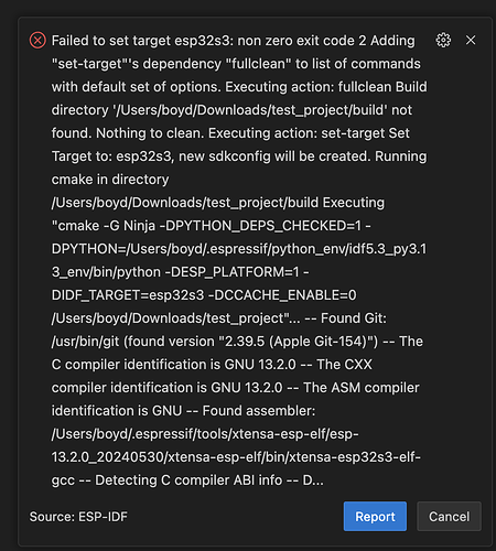
If I try to build anyway:

-- Found Git: /usr/bin/git (found version "2.39.5 (Apple Git-154)")
-- The C compiler identification is GNU 13.2.0
-- The CXX compiler identification is GNU 13.2.0
-- The ASM compiler identification is GNU
-- Found assembler: /Users/boyd/.espressif/tools/xtensa-esp-elf/esp-13.2.0_20240530/xtensa-esp-elf/bin/xtensa-esp32s3-elf-gcc
-- Detecting C compiler ABI info
-- Detecting C compiler ABI info - done
-- Check for working C compiler: /Users/boyd/.espressif/tools/xtensa-esp-elf/esp-13.2.0_20240530/xtensa-esp-elf/bin/xtensa-esp32s3-elf-gcc - skipped
-- Detecting C compile features
-- Detecting C compile features - done
-- Detecting CXX compiler ABI info
-- Detecting CXX compiler ABI info - done
-- Check for working CXX compiler: /Users/boyd/.espressif/tools/xtensa-esp-elf/esp-13.2.0_20240530/xtensa-esp-elf/bin/xtensa-esp32s3-elf-g++ - skipped
-- Detecting CXX compile features
-- Detecting CXX compile features - done
-- git rev-parse returned 'fatal: not a git repository (or any of the parent directories): .git'
-- Could not use 'git describe' to determine PROJECT_VER.
-- Building ESP-IDF components for target esp32s3
CMake Error at /Users/boyd/esp/v5.3.2/esp-idf/tools/cmake/build.cmake:268 (message):
  Failed to resolve component 'lvgl'.
Call Stack (most recent call first):
  /Users/boyd/esp/v5.3.2/esp-idf/tools/cmake/build.cmake:304 (__build_resolve_and_add_req)
  /Users/boyd/esp/v5.3.2/esp-idf/tools/cmake/build.cmake:607 (__build_expand_requirements)
  /Users/boyd/esp/v5.3.2/esp-idf/tools/cmake/project.cmake:710 (idf_build_process)
  CMakeLists.txt:3 (project)


-- Configuring incomplete, errors occurred!

 *  The terminal process "/Applications/CMake.app/Contents/bin/cmake '-G', 'Ninja', '-DPYTHON_DEPS_CHECKED=1', '-DESP_PLATFORM=1', '-B', '/Users/boyd/Downloads/test_project/build', '-S', '/Users/boyd/Downloads/test_project', '-DSDKCONFIG=/Users/boyd/Downloads/test_project/sdkconfig'" terminated with exit code: 1. 

I’ve started a new project and will keep fixing build errors until I’ve got it compiling. Stay tuned. There are 50+ so far. :slight_smile:

See attached ZIP file. I’m getting the following errors at runtime. Also the backlight is not turning on:

I (26) boot: ESP-IDF v5.3.2-dirty 2nd stage bootloader
I (26) boot: compile time Mar 12 2025 14:35:35
I (27) boot: Multicore bootloader
I (30) boot: chip revision: v0.2
I (34) boot: efuse block revision: v1.3
I (38) boot.esp32s3: Boot SPI Speed : 80MHz
I (43) boot.esp32s3: SPI Mode       : DIO
I (48) boot.esp32s3: SPI Flash Size : 2MB
I (52) boot: Enabling RNG early entropy source...
I (58) boot: Partition Table:
I (61) boot: ## Label            Usage          Type ST Offset   Length
I (69) boot:  0 nvs              WiFi data        01 02 00009000 00006000
I (76) boot:  1 phy_init         RF data          01 01 0000f000 00001000
I (84) boot:  2 factory          factory app      00 00 00010000 00100000
I (91) boot: End of partition table
I (95) esp_image: segment 0: paddr=00010020 vaddr=3c060020 size=13e08h ( 81416) map
I (118) esp_image: segment 1: paddr=00023e30 vaddr=3fc93a00 size=02ff0h ( 12272) load
I (121) esp_image: segment 2: paddr=00026e28 vaddr=40374000 size=091f0h ( 37360) load
I (132) esp_image: segment 3: paddr=00030020 vaddr=42000020 size=534cch (341196) map
I (193) esp_image: segment 4: paddr=000834f4 vaddr=4037d1f0 size=067a4h ( 26532) load
I (206) boot: Loaded app from partition at offset 0x10000
I (206) boot: Disabling RNG early entropy source...
I (218) cpu_start: Multicore app
I (227) cpu_start: Pro cpu start user code
I (227) cpu_start: cpu freq: 160000000 Hz
I (227) app_init: Application information:
I (230) app_init: Project name:     ebd4-test
I (235) app_init: App version:      1
I (239) app_init: Compile time:     Mar 12 2025 14:39:38
I (245) app_init: ELF file SHA256:  c277a4b40...
I (251) app_init: ESP-IDF:          v5.3.2-dirty
I (256) efuse_init: Min chip rev:     v0.0
I (261) efuse_init: Max chip rev:     v0.99 
I (266) efuse_init: Chip rev:         v0.2
I (271) heap_init: Initializing. RAM available for dynamic allocation:
I (278) heap_init: At 3FCA7540 len 000421D0 (264 KiB): RAM
I (284) heap_init: At 3FCE9710 len 00005724 (21 KiB): RAM
I (290) heap_init: At 3FCF0000 len 00008000 (32 KiB): DRAM
I (296) heap_init: At 600FE100 len 00001EE8 (7 KiB): RTCRAM
I (303) spi_flash: detected chip: winbond
I (307) spi_flash: flash io: dio
W (311) spi_flash: Detected size(16384k) larger than the size in the binary image header(2048k). Using the size in the binary image header.
I (324) sleep: Configure to isolate all GPIO pins in sleep state
I (331) sleep: Enable automatic switching of GPIO sleep configuration
I (338) main_task: Started on CPU0
I (348) main_task: Calling app_main()
I (348) main_task: Returned from app_main()
I (348) LCD: Init LVGL
I (358) LCD: Init LVGL Display Driver
I (358) gpio: GPIO[15]| InputEn: 1| OutputEn: 1| OpenDrain: 1| Pullup: 1| Pulldown: 0| Intr:0 
I (368) gpio: GPIO[7]| InputEn: 1| OutputEn: 1| OpenDrain: 1| Pullup: 1| Pulldown: 0| Intr:0 
I (378) LCD: Init TCA9554 IO Expander
I (378) LCD: Init SPI3-wire
I (388) gpio: GPIO[1]| InputEn: 0| OutputEn: 1| OpenDrain: 0| Pullup: 0| Pulldown: 0| Intr:0 
I (398) gpio: GPIO[2]| InputEn: 0| OutputEn: 1| OpenDrain: 0| Pullup: 0| Pulldown: 0| Intr:0 
I (408) lcd_panel.io.3wire_spi: Panel IO create success, version: 1.0.1
I (408) LCD: Init ST7701 Driver
I (418) st7701: version: 1.1.1
E (418) lcd_panel.rgb: lcd_rgb_panel_alloc_frame_buffers(165): no mem for frame buffer
E (428) lcd_panel.rgb: esp_lcd_new_rgb_panel(353): alloc frame buffers failed
E (438) st7701_rgb: esp_lcd_new_panel_st7701_rgb(133): create RGB panel failed
E (438) lcd_panel.rgb: esp_lcd_rgb_panel_register_event_callbacks(398): invalid argument
Guru Meditation Error: Core  1 panic'ed (LoadProhibited). Exception was unhandled.

Core  1 register dump:
PC      : 0x42009369  PS      : 0x00060030  A0      : 0x8200955c  A1      : 0x3fcb4240  
--- 0x42009369: init_st7701 at /Users/boyd/Downloads/ebd4-test/main/main.c:367

A2      : 0x00000101  A3      : 0xffffffff  A4      : 0x00000010  A5      : 0x00000003  
A6      : 0x3fc97120  A7      : 0x3c065474  A8      : 0x00000000  A9      : 0x3fcb4210  
A10     : 0x00000102  A11     : 0x3fcb4308  A12     : 0x3fc98084  A13     : 0x3fcb4314  
A14     : 0x3fc93e28  A15     : 0x00000000  SAR     : 0x00000004  EXCCAUSE: 0x0000001c  
EXCVADDR: 0x0000005c  LBEG    : 0x400556d5  LEND    : 0x400556e5  LCOUNT  : 0xfffffff5  
--- 0x400556d5: strlen in ROM
0x400556e5: strlen in ROM


Backtrace: 0x42009366:0x3fcb4240 0x42009559:0x3fcb4340 0x4037b5b9:0x3fcb4370
--- 0x42009366: init_st7701 at /Users/boyd/Downloads/ebd4-test/main/main.c:364
0x42009559: gui_task at /Users/boyd/Downloads/ebd4-test/main/main.c:226
0x4037b5b9: vPortTaskWrapper at /Users/boyd/esp/v5.3.2/esp-idf/components/freertos/FreeRTOS-Kernel/portable/xtensa/port.c:139

ebd4-test-2.zip (44.3 KB)