My ILI9341 display working very slow

hiii
i m a beginner in the display development
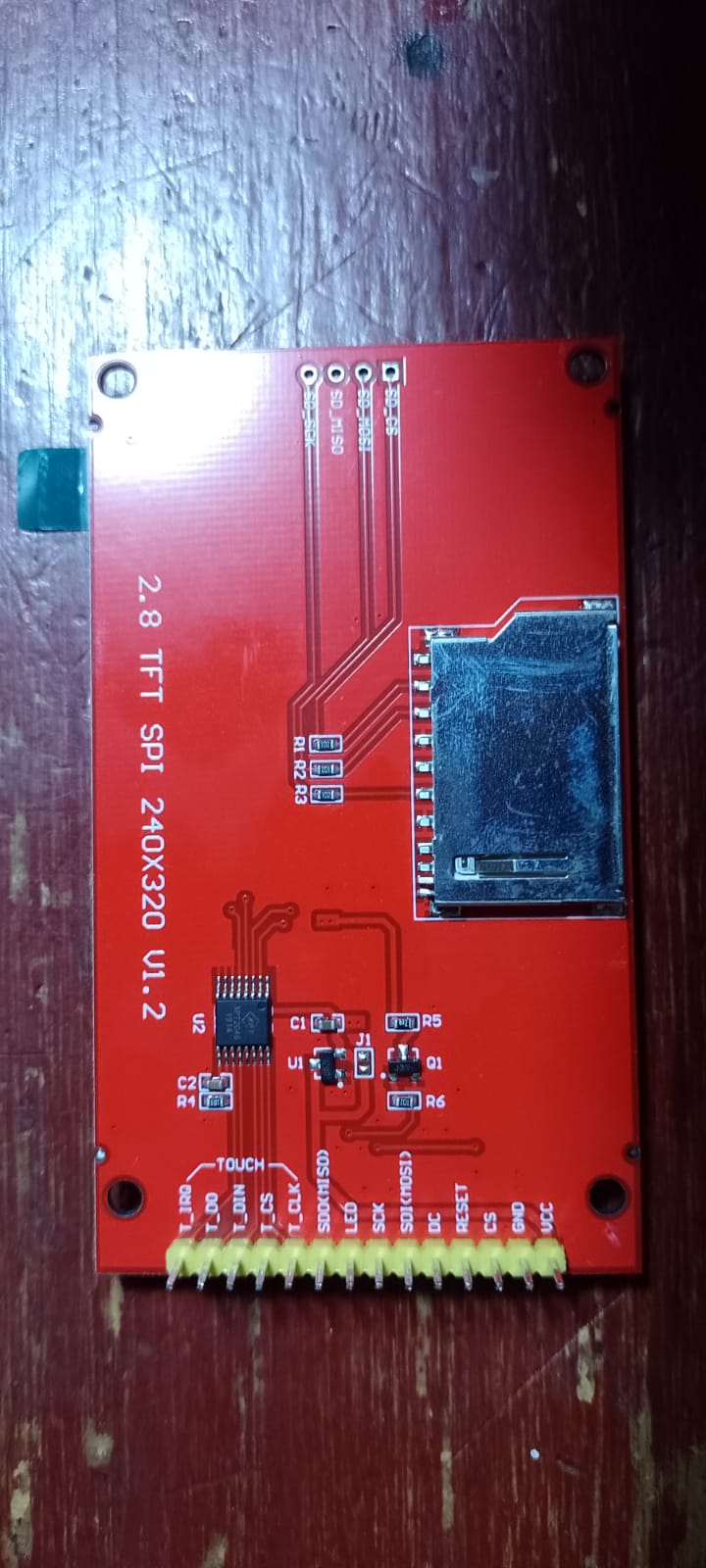
i developed a graphics and touch with ILI9341 320x240 display using spi interface using mcc configuration.
used a MPLAB IDE and PIC32 microcontroller
i use a adafruit gfx library for ili9341 display simple graphics and touch
now i add a littlevgl graphics on it but my display working very slow and behave irritating
video link is given below

video link

my setup code given below

bool my_touchpad_read(lv_indev_drv_t * indev_driver, lv_indev_data_t * data) {
static lv_coord_t last_x = 0;
static lv_coord_t last_y = 0;

/*Save the state and save the pressed coordinate*/
data->state = (isTouching() == 0) ? LV_INDEV_STATE_PR : LV_INDEV_STATE_REL;
if (data->state == LV_INDEV_STATE_PR)getPosition(&last_x, &last_y, 1, 0x10);
lv_tick_inc(1);
/*Set the coordinates (if released use the last pressed coordinates)*/
data->point.x = last_x + 13;
data->point.y = last_y + 4;

return false; /*Return `false` because we are not buffering and no more data to read*/

}

void setup() {

static lv_disp_buf_t disp_buf;
static lv_color_t buf1[LV_HOR_RES_MAX * 10]; /*Declare a buffer for 10 lines*/
static lv_color_t buf2[LV_HOR_RES_MAX * 10]; /*Declare a buffer for 10 lines*/
lv_disp_buf_init(&disp_buf, buf1,buf2, LV_HOR_RES_MAX * 10);
lv_disp_drv_t disp_drv; /*Descriptor of a display driver*/
lv_disp_drv_init(&disp_drv); /*Basic initialization*/
disp_drv.flush_cb = my_disp_flush;
disp_drv.buffer = &disp_buf; /*Assign the buffer to the display*/
lv_disp_t * disp;
disp = lv_disp_drv_register(&disp_drv); /*Finally register the driver*/
lv_indev_drv_t indev_drv;
lv_indev_drv_init(&indev_drv); /*Descriptor of a input device driver*/
indev_drv.type = LV_INDEV_TYPE_POINTER; /*Touch pad is a pointer-like device*/

// indev_drv.type = LV_INDEV_TYPE_NONE;
// indev_drv.read_cb = xpt2046_read; /Set your driver function/
indev_drv.read_cb = my_touchpad_read; /Set your driver function/
lv_indev_drv_register(&indev_drv); /Finally register the driver/
}

void lv_ex_slider_1(void) {
/Create styles/
static lv_style_t style_bg;
static lv_style_t style_indic;
static lv_style_t style_knob;

lv_style_copy(&style_bg, &lv_style_pretty);
style_bg.body.main_color = LV_COLOR_YELLOW; 
style_bg.body.grad_color = LV_COLOR_BLACK;
style_bg.body.radius = LV_RADIUS_CIRCLE;
style_bg.body.border.color = LV_COLOR_BLACK;

lv_style_copy(&style_indic, &lv_style_pretty_color);
style_indic.body.radius = LV_RADIUS_CIRCLE;
style_indic.body.shadow.width = 8;
style_indic.body.shadow.color = style_indic.body.main_color;
style_indic.body.padding.left = 3;
style_indic.body.padding.right = 3;
style_indic.body.padding.top = 3;
style_indic.body.padding.bottom = 3;

lv_style_copy(&style_knob, &lv_style_pretty);
style_knob.body.radius = LV_RADIUS_CIRCLE;
style_knob.body.opa = LV_OPA_70;
style_knob.body.padding.top = 10;
style_knob.body.padding.bottom = 10;

/*Create a slider*/
lv_obj_t * slider = lv_slider_create(lv_scr_act(), NULL);
lv_slider_set_style(slider, LV_SLIDER_STYLE_BG, &style_bg);
lv_slider_set_style(slider, LV_SLIDER_STYLE_INDIC, &style_indic);
lv_slider_set_style(slider, LV_SLIDER_STYLE_KNOB, &style_knob);
lv_obj_align(slider, NULL, LV_ALIGN_CENTER, 0, 0);
// lv_obj_set_event_cb(slider, event_handler1);

}

int main(void) {

SYSTEM_Initialize();
tft_begin();
fillScreen(ILI9341_BLACK);
begin(ILI9341_TFTWIDTH, ILI9341_TFTHEIGHT);
setCalibration(1952, 325, 176, 1696);
lv_init(); 
setup();
lv_ex_slider_1();


while (1) {   
    lv_task_handler();
    lv_tick_inc(10);      

    
}
return 1;

}

1 Like

I had the same thing happen when I was first learning how to use Adafruit’s ILI9341 library.
I was verbosely specifying all of the pins used when I was constructing the Adafruit_ILI9341 class.
I thought I was doing the code a favor.
Turns out I was unknowingly running in to a “feature” that has the display run in Software SPI mode if you provide all of the pins.
Providing only two pins puts it in the much faster Hardware SPI mode.

// https://github.com/adafruit/Adafruit-GFX-Library/blob/master/Adafruit_GFX.h
// https://github.com/adafruit/Adafruit-GFX-Library/blob/master/Adafruit_SPITFT.h
#include <Adafruit_ILI9341.h> // Display Driver https://github.com/adafruit/Adafruit_ILI9341
// Using faster Hardware SPI (HWSPI); Providing MISO/MOSI/CLK results in slower Software SPI (SWSPI)
static Adafruit_ILI9341 display = Adafruit_ILI9341(TFT_CS, TFT_DC, TFT_RST);

I searched the Adafruit Forums and Issues and posted explaining how unintuitive this was and they, even Limor Fried (ladyada) herself, didn’t disagree but said it is like that for Legacy reasons.
‾_(ツ)_/‾

Pv

thanks @paulpv for sharing a valuable info about Adafruit_ILI9341 class.
but i think i have issues about pic32 RAM memory.

have u used a littlevGL ?

One mistake I’ve noted in your code: lv_tick_inc should not be called in my_touchpad_read. Ideally it should be called in a timer interrupt independently of the while(1) loop running lv_task_handler.

I was using my ILI9341 on an ESP32.
Please show the code of your ILI9341 constructor.

And yes, I have used LittlevGL.

Pv

thanks @embeddedt
i called lv_tick_inc in the timer interrupt see below.

void attribute ((vector(_CORE_TIMER_VECTOR), interrupt(IPL1SOFT))) _CORE_TIMER_ISR(void)
{
uint32_t static compare = 0x2EE0;

// Update the compare value
compare = compare + 0x2EE0;

_CP0_SET_COMPARE(compare);

IFS0CLR= 1 << _IFS0_CTIF_POSITION;

lv_tick_inc(100);

}

but that didnt improve speed of display !!!

i post a file of ILI9341.h given below

ILI9341.c (7.1 KB) ILI9341.h (10.4 KB)

and also XPT2046

see that.
XPT2046.c (5.1 KB) XPT2046.h (3.0 KB)

The refresh could be slow in two ways:

  1. You see that the screen is refreshed in blocks (I.e. 20 lines instantly and wait). I’d mean that lvgl needs a lot of time to render a part of the screen but once its ready you can display it fast.
  2. You see that the screen is refreshed line by line. It means lvgl can render the image fast but you send it slowly to the display.

From the video it seems it’s 2) in your case.

How does you my_disp_flush function look like? Do you use drawPixel() in it? If so it will be very slow the send the pixels one by one this way. Instead you should create a function similar to fillRect but with an lv_color_t * parameter instead of a constant color.

It’d be great to know how fast is your SPI and what is the resolution of you display to calculate the theoretical minimum refresh time.

thank you so much @kisvegabor for exact suggestions .

yahh i used a drawPixel() see below.

void my_disp_flush(lv_disp_t * disp, const lv_area_t * area, lv_color_t * color_p) {
uint32_t x, y;

for (y = area->y1; y <= area->y2; y++) {
    for (x = area->x1; x <= area->x2; x++) {
        drawPixel(x, y, color_p->full); /* Put a pixel to the display.*/
        color_p++;
    }
}

lv_disp_flush_ready(disp); /* Indicate you are ready with the flushing*/

}

and for a SPI
i used a 4 Mhz freq.
my display has a 320x240
with
#define LV_DISP_DEF_REFR_PERIOD 1 /[ms]/

This is probably excessive. Setting it to 30 (the default) should be more than fast enough.

As @kisvegabor mentioned above, you’ll get better performance if you inline the drawPixel routine into your code, and optimize it to send as little through SPI as possible.

For example, many drawPixel routines send a command to set the X and Y cursor/window, then send one pixel’s color value, then return. That means you end up setting the cursor for every pixel.

This is grossly inefficient compared to a fillRect function, which would set the cursor/window once and then send many pixels (at least one row, possibly more).

It depends on the number of commands your particular display controller needs, but using my simplified example, I think you could easily cut your total number of SPI transfers in half, which should be a significant boost to performance.

thank you @embeddedt and @kisvegabor

finally my GUI has been working perfectly after putting default LV_DISP_DEF_REFR_PERIOD values…

Hello, im new in electronics. i have the same problem he talks about in this topic, but en up using the 2 pins call being CS and DC, but the problem is that when i use that call, my screen doesn´t works, it only display when i conect CS to ground, i try to serch in the code but i dont know what can it be, i use the graphictests.ino that comes with the library ILI9341, and im using a ESP32. i dont understand why when i use all pins call it work but when i use the 2 pins call it doesn´t work

Some pins is input only, maybe this is isssue

There is an issue with a display and the CS pin. I don’t remember how to identify it. Let me look and see if I can locate the information on it.

it’s not the CS line, it’s with the SPI going tristate.

But here it is anyhow.

scratch that. The problem is on the CS line.

How can I resolve that? I saw that this happened in V1.0 my screen says V1.2. how can I be assured that that is the problem?

I am not seeing any diodes on your display only resistors and caps so you should be good.

Lets make sure you understand the pin outs on the board.

you have T_IRQ which is an interrupt for the touch screen. You do not need to use this as LVGL polls the touch screen for data. the T_DO is MOSI and the T_DIN is MISO for touch screen data. then you have the T_CS which is the cable/chip select for the touch interface and you have the T_CLK which is the SPI clock

Now you have a choice on how you want to run this display. You can use a single SPI bus and connect the SPI for the display and also the SPI for the touch to that single bus. You have to make sure that the CS line gets driven low to the touch or display when you are going to send data to it and then you need to drive the CS high when it is not being written to. DO NOT let the CS float as this can cause issues. Optionally you can separate the 2 onto 2 different SPI busses. The cost is going to be additional pins to do this. If you use 2 different SPI busses then you can connect the CS to ground and leave it that way so long as those are the only things on the busses. Optionally you can disconnect the MISO line for the display and save a GPIO on the MCU. So this is the pin connections

T_IRQ: not needed
T_DO: MISO for the touch (required)
T_DIN: MOSI for the touch (required)
T_CS: chip/cable select for the touch (grounded if the touch is on it’s own SPI bus)
T_CLK: SPI clock (required)
SDO: MISO for the display (optional)
LED: backlight (optional, connect to VCC if not connected to MCU)
SCK: SPI clock for the display (required)
SDI: MOSI for the display (required)
DC: data transmit (required)
CS: chip/cable select for the display (same as the CS for the touch).

Me personally I would run the display and touch on separate busses. I believe that the touch interface is going to operate at a lower frequency than the display and this will limit the speed. Depending on what MCU you are using is also going to dictate the speeds the SPI is going to run at. The SPI is the single largest bottleneck so anything you can do to help speed up the transfer rate you should do.

To connect the display and touch to 2 separate busses you would need at a minimum 6 GPIO pins. if using a library like TFT-espi then you will not be able to use it’s internal touch screen driver. This is because it is written so that the display and the touch is always on the same bus. You would have to use a second library to handle the touch screen