and SVG should be rendered using beziers. That is what makes the curves. if you render an SVG using polygons you are going to need to use a hell of a lot of points to make a curved shape look curved. rendering an arc can also be done using a bezier with 4 points.
as far as utility functions go the ability to set a “Pen” or “Brush” could be really useful. a Pen would be an outline and the brush would be the background. the idea behind that is the ability to set a gradient as the brush or an image as a brush. the pen can have it’s width changed and also the style. dots, dashes, dots and dashes. A Pen can also have its ends changed to Rounded, squared, mitered (when meeting another line) that kind of thing.
a pen and a brush would each be a structure and the structures would get passed to the CTX and every time something is drawn they are used. If the user wants to change the pen or brush they are able to do so.
It is actually a better way to do it from a performance standpoint. Right now if I want to render a rectangle I have to initialize a lv_draw_rect_dsc_t structure which is where all the color information is stored. If I wanted to render an arc after that rectangle but using the same colors I am not able to just pass the information to the CTX in order to render the arc. I have to create a lv_draw_arc_dsc_t structure and pass that to the draw CTX with the color information replicated in that structure. Even tho I want to sue the same colors. So an additional bunch of bytes needs to be used for no real purpose.
Rendering a shadow would work under the same idea except a function would be called to render it. The brush would be used to render the shadow.
Here is the rect structure. There is a lot stuffed into that one structure that may or may not even get used by a user when rendering.
typedef struct {
    lv_coord_t radius;
    lv_blend_mode_t blend_mode;

    /*Background*/
    lv_opa_t bg_opa;
    lv_color_t bg_color;        /**< First element of a gradient is a color, so it maps well here*/
    lv_grad_dsc_t bg_grad;

    /*Background img*/
    const void * bg_img_src;
    const void * bg_img_symbol_font;
    lv_color_t bg_img_recolor;
    lv_opa_t bg_img_opa;
    lv_opa_t bg_img_recolor_opa;
    uint8_t bg_img_tiled;

    /*Border*/
    lv_color_t border_color;
    lv_coord_t border_width;
    lv_opa_t border_opa;
    uint8_t border_post : 1;        /*There is a border it will be drawn later.*/
    lv_border_side_t border_side : 5;

    /*Outline*/
    lv_color_t outline_color;
    lv_coord_t outline_width;
    lv_coord_t outline_pad;
    lv_opa_t outline_opa;

    /*Shadow*/
    lv_color_t shadow_color;
    lv_coord_t shadow_width;
    lv_coord_t shadow_ofs_x;
    lv_coord_t shadow_ofs_y;
    lv_coord_t shadow_spread;
    lv_opa_t shadow_opa;
} lv_draw_rect_dsc_t;
rendering a shadow should be a function. rendering the border would be done at the time the rect is rendered using the set Pen. image rendering is a function call, background get rendered at the time the rectangle is rendered.
This is pseudo code so as an example. Say the screen size is 480 x 320. the screen color is set to 0xFFFFFF
ctx = get_ctx();
lv_pen_t pen;
lv_brush_t brush;

lv_area_t rect;
rect.x1 = 156;
rect.y1 = 114;
rect.x2 = 321;
rect.y2 = 203;

pen.color = lv_color_hex(0x00FF00);
pen.opa = 125;
pen.style= LV_PEN_MITERED | LV_PEN_STYLE_SOLID
pen.width=4;

brush.color = lv_color_hex(0x0000FF);
brush.opa = 255;

lv_ctx_set_pen(ctx, pen);
lv_ctx_set_brush(ctx, brush);

// now we render the rectangle
lv_draw_rect(ctx, rect);
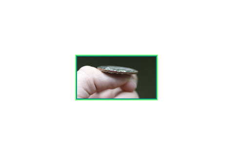
That produces this

Note how the border looks beveled. That is because the rect is rendered at the coords given and then the border is rendered using those coords so 1/2 of the pen width is over the background and the other 1/2 is not. Since you used an alpha value of 125 you end up with what looks like a beveled edge
we extend that code further to include
rect.x1 = rect.x1 + 2;
rect.y1 = rect.y1 + 2;
rect.x2 = rect.x2 - 2;
rect.y2 = rect.y2 - 2;


// rendering an image would use the brush as the mechanism to do a recolor., we do not want to recolor the image so set it to a transparent brush

lv_set_brush(ctx, LV_TRANSPARENT_BRUSH);

// render the image
lv_draw_img(ctx, rect, img_data);
and now you end up with this.

a function for rendering a rectangle with rounded corners
lv_draw_rounded_rect(ctx, rect, 10);

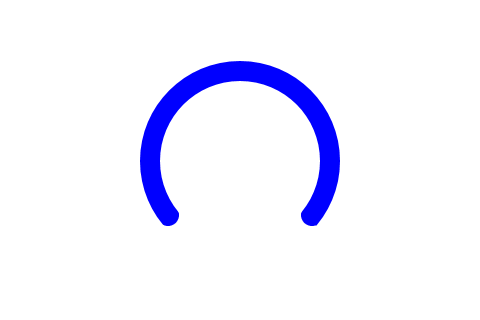
an arc in lvgl is really a partial circle so lets just call it a circle. a circle can be rendered 2 ways, using a center point and a radius or it can be rendered using a bounding box (rect) where it is going to use the smaller of the width or height to determine the radius and center. easiest way to go about this is going to be using a rect or an lv_area_t structure because that is a common thing to use. no need to make it more complex or add anything additional to render an arc. an “arc” that makes a complete circle would use the brush to fill in the circle otherwise only the pen is used so to
ctx = get_ctx();
lv_pen_t pen;

pen.color = lv_color_hex(0x0000FF);
pen.opa = 255;
pen.style= LV_PEN_ROUNDED_ENDS | LV_PEN_STYLE_SOLID
pen.width=20;

lv_ctx_set_pen(ctx, pen);
lv_set_brush(ctx, LV_TRANSPARENT_BRUSH);

lv_area_t rect;
rect.x1 = 140;
rect.y1 = 60;
rect.x2 = 340;
rect.y2 = 260;

lv_draw_arc(ctx, rect, 1350, 4050);
and the result is this.

allowing the objects to be reused by placing common parts into a structure that is able to be shared between all rendering functions is going to save resources. with manipulating how things are rendered like the rectangle you can actually kill 2 birds with one stone, the outline and the border is a good example if they are after making a beveled edge. even still by being able to set the background to a transparent brush a small change to the size of the rectangle being drawn they are able to render the outline pretty easily. You can also eliminate the repeated function calls for rendering by adding functions that render arrays. so for rendering rectangles an array of rectangles get passed and optionally an array of pens and/or an array of brushes.


