I’m trying to get a purely yellow font for a label. My display uses the st7789. I’m using LVGL v9.4.0. My panel is configured as 16 bits per pixel and RGB color scheme (LV_COLOR_FORMAT_RGB565). The code I’m using is as follows:
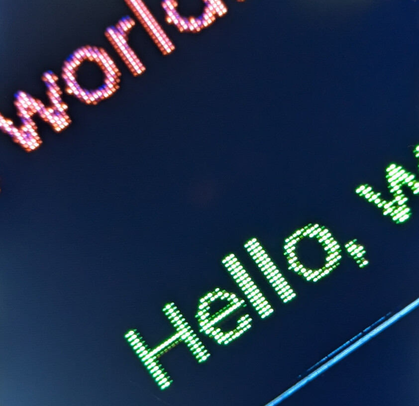
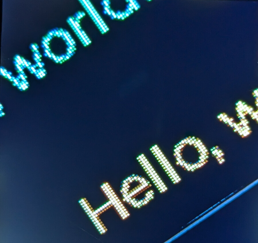
When I use this code, the text is mostly yellow but there are some strange artifacts, Some of the pixels in a couple of the letters are red, and some are green. Although when looking at the text it looks basically yellow, it’s very noticeably a bit off color in some bits of it.
I tested the color scheme by displaying a solid yellow rectangle and the rectangle appears purely yellow, with all yellow pixels.
This sort of issue occurs with Cyan and Magenta as well but far less noticeable as the stray colors are close to the primary.
I think I understand what may be happening. I’m seeing something similar on primary color text but it’s much more subtle (some pixels same color but darker). It seems that the library may be trying to do some anti-aliasing of the font using color? I’m not sure. The effect is still a bit odd with the yellow for sure as it looks discolored. With some primary colors, letters such as capital “H” look like one leg of the H is thinner than the other leg.
can you take a photo of what it looks like and attach it to a post in this topic. I would like to see what you are talking about…
You could have a setting wrong for the display initialization or if you are using a separate display and MCU possibly a bad connect5ion between the display and the MCU. Another thing that could be causing it is the connection or “bus” type you are using and possibly the speed of the bus is too fast. I am guessing that you are using an ESP32 since you posted in an ESP32 thread. The ESP32 can be a bit fickle with what ins are being used in combination with pieces of built in hardware. Things like the WiFi can sometimes cause anomalies to appear on the screen depending on what GPIO’s are being used.
you can print out the RGB565 values from the frame buffer in the flush function. That will tell you if what you are seeing is being caused by LVGL or the hardware. That would be the easiest way to go about it.
If you are setting the font color to FFFF00 then cast the buffer passed to the flush function to a uint16_t* and use uint32_t size = lv_area_get_size(area); to get the size from the lv_area_t pointer that is passed to the flush function. Then a simple for loop to get the indexes needed to access each pixel in the frame buffer. Filter out pixels that are not.
Here is some pseudo code. This code has not been tested and may have errors in it Read the comments in the code.
void flush(lv_display_t *disp, lv_area_t *area, uint8_t *buf)
{
    uint16_t pixel;
    int16_t red;
    int16_t green;
    int16_t blue;

    uint16_t *buf16 = (uint16_t *)buf;

    uint32_t size = lv_area_get_size(area);

    for (uint32_t i=0;i<size;i++) {
        pixel = buf16[i];

        red = (int16_t)((pixel & 0xF800) >> 8);
        green = (int16_t)((pixel & 0x07E0) >> 2);
        blue = (int16_t)((pixel & 0x001F) << 3);

        if ((red < green - 5) || (red > green + 5) ||
            (green < red - 5) || (green > red + 5) ||
            (blue != 0)) {

            // code to print out red, green, blue
        }
    }

    // The rest of the flush function code goes here.
}
Hello @kdschlosser, thanks very much for the detailed response.
I did previously try taking a pic with my phone but the color process in the photo was poor and the artifact would not show up. I’ll see if I can set up a magnifier and take a photo through that.
Do you know how to write Python code? It’s really easy to do if you don’t. You can try out a project I have been working on for LVGL and MicroPython. It include all of the display drivers and the bus drivers. Everything is ready to go you just need to compile it and then flash the binary to the ESP32 and then upload the python script to the ESP32.
You can give that a shot if you want to see if the artifacts still show up.
Lemme know if you want to give that a go and I will tell you what you need to do.
Yes, I know python, although I have not tried MicroPython for ESP32. I can take your code for a spin and see what happens. I’ll also try the buffer read/flush when I get a chance.
Meanwhile, I used a cheap PCB magnifier I have to try to get some images. These still aren’t great. Between the magnifier and the phone camera, the color gamut gets munged. But you can see what’s going on at least, I think.
With the naked eye, the discoloration in some letters is evident and it just doesn’t look very good. I should have take a pic of the Red “H”. It looks particular bad with a naked eye, looking like the left leg of the H is one pixel width, and the right leg appears 2 or 3 in width.
I was going to try turning off anti-aliasing in LVGL, but I noticed they removed the ability to do so in version 9.
if you have an android device download a program called “Magnifier & Microscope”… You will love this application… It should solve your issue of using a magnifying glass and a phone camera and the colors seem to be close to being correct.
That application handles the USB redirect to WSL. You will want to flash the firmware from WSL because the program to do that will be installed into WSL…
Read the README.md file as it will tell you what you need to do in order to build. Once you have the linux/maxOS requirements met the build command is a single line and the build system will take care of collecting and setting up the things needed to create a proper build environment.
Once you get up to the point of building let me know and I will provide you with the build command you are going to want to use. Optionally you can read the rest of the readme file and it will tell you all of the options to build and you can set them accordingly.
The board I have is an odd-ball (read: cheapo from Amazon) … and Ideaspark CH340. It has an ESP32 WROOM processor, 8MB of flash. Let me know what the next steps are. Thanks!
You like how nice and easy it was to compile? You don’t need to mess around with setting up the ESP-IDF or any other library requirements. It handles everything for you. Compiling MicroPython is actually a quite involved thing to do and then add in there generating the binding code and building LVGL as well as the bus drivers… There is a lot to it.
what does it have for SPIRAM?
Does your display have a touch screen?
OK so you are going to want to add --flash-size=8 to your build command and if you have SPIRAM you will need to add BOARD_VARIANT=SPIRAM to the build command.
Those are the only 2 additional things that are needed unless you have a touch screen and if you do have one then you will add INDEV={ic model number} replacing {ic model number} with the model number of the touch IC you are using.
Once it has finished compiling the last few lines of code tell you how to write the firmware to the ESP. You will need to replace the {PORT} with the port that your ESP is plugged into. you can locate this by going to /dev/serial and locating the file that is for the ESP32. the full path to that file is what you enter for the port. Compiling is also going to be a lot faster, all the requirements have been downloaded and setup which takes a bit of time to do.
If you tell me the pins your display is connected to on the ESP I can key you up a working example.
the nice thing about the binding is it takes care of most things under the hood so you don’t need to worry about it. You can jump right into writing the GUI. It handles creating the frame buffer(s) and allocating the buffers into DMA memory if there is enough memory available that is DMA’able. It handles flushing and rotation, etc…
The API takes a but of getting used to. It is a more pythonic API so the widgets are classes and all of the attribute functions for changing background color, size, etc… are all methods of the classes. There are a few tweaky things with it because of the garbage collection in MicroPython and needing to keep things like callback functions in scope otherwise they will get GC’d and when LVGL tries to access the callback function it’s not going to be able to and a crash will occur. It’s pretty common sense kinds of things when programming.
I did my best to make it as simple to get up and running and to use as possible.
Hi Kevin, thanks for the helpful info.
My LCD screen has no input (including touch) so nothing there.
This board doesn’t come with much in the way of specs, so I don’t know if it has SPIRAM. I suspect it doesn’t as it’s not mentioned anywhere.
How are the GPIO numbers used for SPI interface to be specified?
as integers. These numbers are the actual GPIO numbers and may not typically align with what might be printed on the PCB You can usually find a diagram somewhere that indicates a pin to GPIO number mapping…
There is a feature in the build system that will automatically generate the code to get your display and board up and running. It will bake that code into a python module named display.
create a file named my_display_driver.toml, you can name it whatever you like so long as it has .toml on the end of it.
you will need to modify the information above to the GPIO numbers will align with what you have for your hardware. If your hardware doesn’t use some of the pins you can simply change that number to -1 or you can delete that line entierly in most cases. the dc, cs and miso MUST be listed even if they are not being used. In this case you change them to a -1, pins like backlight and power can simply be removed.
to use the toml feature you are going to need to install the toml library into the python you are using… That can be achieved by running the following command
pip3 install toml
The build command you will use has to change in order to use the toml file.
once you build and flash the firmware connect to the ESP32 using a serial terminal program. anything will typically work. I am running on Windows and will typically use Putty and sometimes Realterm.
when you connect to the ESP32 you may or may not see a Python REPL prompt >>>. if you do not see it press the enter key and then it should come up.
copy and paste each of the following lines of code pressing enter after each line…
import lvgl as lv
import display

scrn = lv.screen_active()

text = lv.label(scrn)
text.set_text('Hello World')
text.set_style_text_color(lv.color_hex(0xFFFF00), lv.PART.MAIN)
text.center()
and that should get the job done for ya.
It will be using the default font which I believe is the 14 point one.