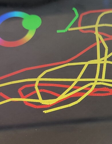
Lv_canvas_draw_line, smoother curve?

Hello,
When I use the following function, there is always a glitch between the lines (see image below).
Is there a way to avoid this, or to draw a smoother curve?

I’m using lvgl version 8.3.2

Thank you

lv_canvas_draw_line(ui.screen_1_canvas_1, points, 2, &draw_line_dsc);

when I change following parameter, nothing happen, why?

lv_draw_line_dsc_t draw_line_dsc =
{
.round_end = 250,
.round_start = 250,
.dash_gap = 150,
.raw_end = 250
};

Hello,

I think you are looking in the wrong direction here. I don’t have time to test LVGL right now, but looking at one of the examples in the documentation:

void lv_example_line_1(void)
{
    /*Create an array for the points of the line*/
    static lv_point_t line_points[] = { {5, 5}, {70, 70}, {120, 10}, {180, 60}, {240, 10} };

    /*Create style*/
    static lv_style_t style_line;
    lv_style_init(&style_line);
    lv_style_set_line_width(&style_line, 8);
    lv_style_set_line_color(&style_line, lv_palette_main(LV_PALETTE_BLUE));
    lv_style_set_line_rounded(&style_line, true);

    /*Create a line and apply the new style*/
    lv_obj_t * line1;
    line1 = lv_line_create(lv_scr_act());
    lv_line_set_points(line1, line_points, 5);     /*Set the points*/
    lv_obj_add_style(line1, &style_line, 0);
    lv_obj_center(line1);
}

Getting a smoother line should be as simple as setting the style using lv_style_set_line_rounded if the example is correct.

when I use “lv_style_t” instead “lv_draw_line_dsc_t” I do not see any line :frowning:

//lv_canvas_draw_line(ui.screen_1_canvas_1, points, 2, &draw_line_dsc); lv_canvas_draw_line(ui.screen_1_canvas_1, points, 2, &style_line);

I see. Apparently for canvases you need to use a draw descriptor (lv_draw_line_dsc_t)
of a line instead of an actual line object…

I would suggest having a look at the lv_draw_line_dsc_t members.
In your earlier post you have already done this, perhaps those setting just don’t produce any meaningful output. I am guessing setting round_end and round_start to the same value already ruins this, for instance.

Here is the struct definition from lv_draw_line.h:

/**********************
 *      TYPEDEFS
 **********************/
typedef struct {
    lv_draw_dsc_base_t base;

    lv_point_t p1;
    lv_point_t p2;
    lv_color_t color;
    lv_coord_t width;
    lv_coord_t dash_width;
    lv_coord_t dash_gap;
    lv_opa_t opa;
    lv_blend_mode_t blend_mode  : 2;
    uint8_t round_start : 1;
    uint8_t round_end   : 1;
    uint8_t raw_end     : 1;    /*Do not bother with perpendicular line ending if it's not visible for any reason*/
} lv_draw_line_dsc_t;

I would suggest not touching dash_width and gap, as these sound like settings for dashed lines. Only round start and end should be of interest I think.

Aaah, great. I changed too many parameters and started with values that were too large; that seems to have messed everything up. The following is working, but not perfect.
Where can I find documentation or explanation about the function of these parameters?

lv_draw_line_dsc_init(&draw_line_dsc); 
draw_line_dsc.color = color; 
draw_line_dsc.width = 10;
draw_line_dsc.round_end = 3;

I wish I knew… It is indeed a bit vague.

@kisvegabor sorry for tagging, but you are probably the only person that knows whether or not these parameters are documented.

There’s no information in the docs, but you can sort of guess the meaning of the descriptor members, which is not ideal. From master (aka v9):

typedef struct {
    lv_draw_dsc_base_t base;

    lv_point_t p1;
    lv_point_t p2;
    lv_color_t color;
    lv_coord_t width;
    lv_coord_t dash_width;
    lv_coord_t dash_gap;
    lv_opa_t opa;
    lv_blend_mode_t blend_mode  : 2;
    uint8_t round_start : 1;
    uint8_t round_end   : 1;
    uint8_t raw_end     : 1;    /*Do not bother with perpendicular line ending if it's not visible for any reason*/
} lv_draw_line_dsc_t;

E.g. the round_start and round_end are 1 bit wide, so you can enable or disable them. For the blend_mode you could reference the lv_blend_mode_t enum, etc.

There really needs to be an option to miter the ends. This would draw them properly passing an array of start and end points to render lines. If the line ends occupy the same coordinates then the ends would be mitered together.

As a solution you can render triangles on the ends of the lines to make your own miters. I know it would be an additional thing you would have to code in to do bit it shouldn’t be that hard to do the angle math to figure out where the 3 points need to be places at each end to make it miter properly.

Here is an example written in Python. You should be able to convert it to C code pretty easily.

##### startup script #####

#!/opt/bin/lv_micropython -i

import lvgl as lv
import display_driver
import math


##### main script #####

CANVAS_WIDTH  = 420
CANVAS_HEIGHT = 320

LV_COLOR_SIZE = 32

#
# Draw a line to the canvas
#

# Create a buffer for the canvas
cbuf = bytearray((LV_COLOR_SIZE // 8) * CANVAS_WIDTH * CANVAS_HEIGHT)

# Create a canvas and initialize its palette
canvas = lv.canvas(lv.scr_act())
canvas.set_buffer(cbuf, CANVAS_WIDTH, CANVAS_HEIGHT, lv.COLOR_FORMAT.NATIVE)
canvas.fill_bg(lv.color_hex3(0xccc), lv.OPA.COVER)
canvas.center()

ldsc1 = lv.draw_line_dsc_t()
ldsc1.init()

ldsc1.color = lv.palette_main(lv.PALETTE.RED)
ldsc1.width = 10
ldsc1.round_end = 0
ldsc1.round_start = 0
ldsc1.p1.x = 50;
ldsc1.p1.y = 50;
ldsc1.p2.x = 100;
ldsc1.p2.y = 100;

ldsc2 = lv.draw_line_dsc_t()
ldsc2.init()

ldsc2.color = lv.palette_main(lv.PALETTE.RED)
ldsc2.width = 10
ldsc2.round_end = 0
ldsc2.round_start = 0
ldsc2.p1.x = 150;
ldsc2.p1.y = 75;
ldsc2.p2.x = 100;
ldsc2.p2.y = 100;

layer = lv.layer_t()
canvas.init_layer(layer);

lv.draw_line(layer, ldsc1)
lv.draw_line(layer, ldsc2)


p1 = lv.point_t()

def _get_angle(x1, y1, x2, y2):
    return math.degrees(math.atan2(y1 - y2, x1 - x2))

def _point_on_circle(degree, center_x, center_y, radius):
    radians = math.radians(degree)
    x = int(round(center_x + (radius * math.cos(radians))))
    y = int(round(center_y + (radius * math.sin(radians))))

    p = lv.point_t()
    p.x = x
    p.y = y
    return p


if ldsc2.p1.x == ldsc1.p1.x and ldsc2.p1.y == ldsc1.p1.y:
    p1.x = ldsc2.p1.x
    p1.y = ldsc2.p1.y

    angle1 = _get_angle(p1.x, p1.y, ldsc1.p2.x, ldsc1.p2.y)
    angle2 = _get_angle(p1.x, p1.y, ldsc2.p2.x, ldsc2.p2.y)


elif ldsc2.p2.x == ldsc1.p2.x and ldsc2.p2.y == ldsc1.p2.y:
    p1.x = ldsc2.p2.x
    p1.y = ldsc2.p2.y

    angle1 = _get_angle(p1.x, p1.y, ldsc1.p1.x, ldsc1.p1.y)
    angle2 = _get_angle(p1.x, p1.y, ldsc2.p1.x, ldsc2.p1.y)

elif ldsc2.p2.x == ldsc1.p1.x and ldsc2.p2.y == ldsc1.p1.y:
    p1.x = ldsc2.p2.x
    p1.y = ldsc2.p2.y

    angle1 = _get_angle(p1.x, p1.y, ldsc1.p2.x, ldsc1.p2.y)
    angle2 = _get_angle(p1.x, p1.y, ldsc2.p1.x, ldsc2.p1.y)

else:
    raise RuntimeError('no matching ends')


angle_dif = angle2 - angle1

print(angle_dif)

radius1 = ldsc1.width / 2
radius2 = ldsc2.width / 2


# this is to make an adjustment caused by floating point math.
if angle_dif == 90:
    radius1 += 2
    radius2 += 2
elif angle_dif > 90:
    radius2 += 1

p2 = _point_on_circle(angle1 + 90, p1.x, p1.y, radius1)
p3 = _point_on_circle(angle2 - 90, p1.x, p1.y, radius2)

print(p2.x, p2.y)
print(p3.x, p3.y)
    
tdsc = lv.draw_triangle_dsc_t()
tdsc.init()

tdsc.p = [p1, p2, p3]

tdsc.bg_color = lv.palette_main(lv.PALETTE.RED)
tdsc.bg_opa = lv.OPA.COVER

lv.draw_triangle(layer, tdsc)

canvas.finish_layer(layer)

This is using version 9.0 so if you are using version 8.x then you will need to make some code changes to make it work.

You can paste the code above into the simulator. Here is a link to the simulator, just overwrite the code in it and press the “restart” button at the top

https://sim.lvgl.io/v9.0/micropython/ports/javascript/index.html

You will have to tweak the code so it will support both positive and negative angles but that shouldn’t be that hard to do.