Description
Hi there,
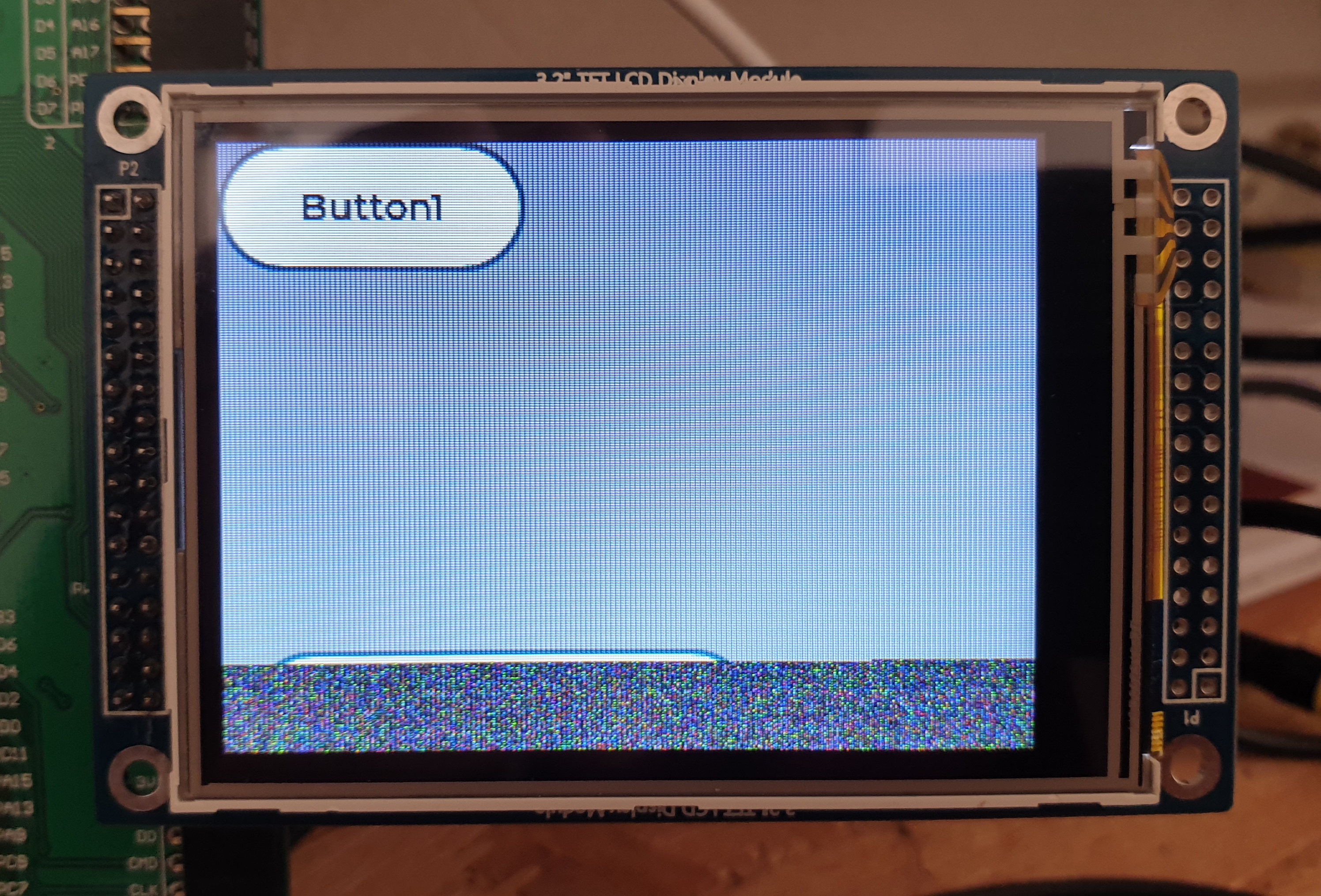
I’m trying to port LVGL to be used with a STM32F407 (on the STM32F4-DISCO board), and had success after following the porting guide and using the less efficient flush_cb that writes pixel by pixel to memory. When I later try to use DMA, and do as in the lv_port_stm32F429_disco repository, I can see how first screen is written to the display, but not all of it (20-30 lines left, which keep random noise).
After this point, if I try to write some more objects to the display, nothing else shows up
What MCU/Processor/Board and compiler are you using?
STM32F407, STM32F4-DISCO, gcc, LVGL 7.1, and ILI9325 320x240 Display
What do you want to achieve?
Port LVGL to this MCU + Display, using DMA buffer transfer
What have you tried so far?
I tried to write to the display pixel by pixel, manually copying the lvgl buffer to the display buffer, with successful results:
static void my_flush_cb(lv_disp_drv_t *disp_drv, const lv_area_t *area, lv_color_t *color_p) {
  int32_t x, y;

  for (y = area->y1; y <= area->y2; y++) {
    for (x = area->x1; x <= area->x2; x++) {

      ili9325_WritePixel(x, y, color_p->full);
      color_p++;

    }
  }
  lv_disp_flush_ready(disp_drv);
}
But when I configure it to use DMA, the display is not showing the image on the whole surface, showing random data on the last 20 - 30 lines, and the data is updated no more, as if it would be writing to a wrong memory place and device display would halt. (Program in MCU continues)
Code to reproduce
static __IO uint16_t * my_fb = (__IO uint16_t *) 0x60020000;

static lv_disp_drv_t disp_drv;
static int32_t x1_flush;
static int32_t y1_flush;
static int32_t x2_flush;
static int32_t y2_fill;
static int32_t y_fill_act;
static lv_color_t *buf_to_flush;

static void my_flush_cb(lv_disp_drv_t *disp_drv, const lv_area_t *area, lv_color_t *color_p) {

  /*Return if the area is out the screen*/
  if (area->x2 < 0) return;
  if (area->y2 < 0) return;
  if (area->x1 > DISP_HOR_RES - 1) return;
  if (area->y1 > DISP_VER_RES - 1) return;

  /*Truncate the area to the screen*/
  int32_t act_x1 = area->x1 < 0 ? 0 : area->x1;
  int32_t act_y1 = area->y1 < 0 ? 0 : area->y1;
  int32_t act_x2 = area->x2 > DISP_HOR_RES - 1 ? DISP_HOR_RES - 1 : area->x2;
  int32_t act_y2 = area->y2 > DISP_VER_RES - 1 ? DISP_VER_RES - 1 : area->y2;

  x1_flush = act_x1;
  y1_flush = act_y1;
  x2_flush = act_x2;
  y2_fill = act_y2;
  y_fill_act = act_y1;
  buf_to_flush = color_p;


  /*##-7- Start the DMA transfer using the interrupt mode #*/
  /* Configure the source, destination and buffer size DMA fields and Start DMA Stream transfer */
  /* Enable All the DMA interrupts */
  HAL_StatusTypeDef err;
  err = HAL_DMA_Start_IT(&hdma_memtomem_dma2_stream0,
                         (uint32_t) buf_to_flush,
                         (uint32_t) &my_fb[y_fill_act * DISP_HOR_RES + x1_flush],
                         (x2_flush - x1_flush + 1));
  if (err != HAL_OK) {
    while (1);    /*Halt on error*/
  }
}

void DMA_TransferComplete(DMA_HandleTypeDef *han) {

  y_fill_act++;

  if (y_fill_act > y2_fill) {
    lv_disp_flush_ready(&disp_drv);
  } else {
      buf_to_flush += x2_flush - x1_flush + 1;
    /*##-7- Start the DMA transfer using the interrupt mode ####################*/
    /* Configure the source, destination and buffer size DMA fields and Start DMA Stream transfer */
    /* Enable All the DMA interrupts */
    if (HAL_DMA_Start_IT(han, (uint32_t) buf_to_flush, (uint32_t) &my_fb[y_fill_act * DISP_HOR_RES + x1_flush],
                         (x2_flush - x1_flush + 1)) != HAL_OK) {
      while (1);    /*Halt on error*/
    }
  }
}

void MX_DMA_Init(void)
{
  /* DMA controller clock enable */
  __HAL_RCC_DMA2_CLK_ENABLE();

  /* Configure DMA request hdma_memtomem_dma2_stream0 on DMA2_Stream0 */
  hdma_memtomem_dma2_stream0.Instance = DMA2_Stream0;
  hdma_memtomem_dma2_stream0.Init.Channel = DMA_CHANNEL_0;
  hdma_memtomem_dma2_stream0.Init.Direction = DMA_MEMORY_TO_MEMORY;
  hdma_memtomem_dma2_stream0.Init.PeriphInc = DMA_PINC_ENABLE;
  hdma_memtomem_dma2_stream0.Init.MemInc = DMA_MINC_ENABLE;
  hdma_memtomem_dma2_stream0.Init.PeriphDataAlignment = DMA_PDATAALIGN_HALFWORD;
  hdma_memtomem_dma2_stream0.Init.MemDataAlignment = DMA_MDATAALIGN_HALFWORD;
  hdma_memtomem_dma2_stream0.Init.Mode = DMA_NORMAL;
  hdma_memtomem_dma2_stream0.Init.Priority = DMA_PRIORITY_HIGH;
  hdma_memtomem_dma2_stream0.Init.FIFOMode = DMA_FIFOMODE_ENABLE;
  hdma_memtomem_dma2_stream0.Init.FIFOThreshold = DMA_FIFO_THRESHOLD_1QUARTERFULL;
  hdma_memtomem_dma2_stream0.Init.MemBurst = DMA_MBURST_SINGLE;
  hdma_memtomem_dma2_stream0.Init.PeriphBurst = DMA_PBURST_SINGLE;
  if (HAL_DMA_Init(&hdma_memtomem_dma2_stream0) != HAL_OK)
  {
    Error_Handler();
  }

  /* DMA interrupt init */
  hdma_memtomem_dma2_stream0.XferCpltCallback = DMA_TransferComplete;
  /* DMA2_Stream0_IRQn interrupt configuration */
  HAL_NVIC_SetPriority(DMA2_Stream0_IRQn, 0, 0);
  HAL_NVIC_EnableIRQ(DMA2_Stream0_IRQn);

}

void MX_FSMC_Init(void)
{
  FSMC_NORSRAM_TimingTypeDef Timing = {0};

  /** Perform the SRAM1 memory initialization sequence
  */
  hsram1.Instance = FSMC_NORSRAM_DEVICE;
  hsram1.Extended = FSMC_NORSRAM_EXTENDED_DEVICE;
  /* hsram1.Init */
  hsram1.Init.NSBank = FSMC_NORSRAM_BANK1;
  hsram1.Init.DataAddressMux = FSMC_DATA_ADDRESS_MUX_DISABLE;
  hsram1.Init.MemoryType = FSMC_MEMORY_TYPE_SRAM;
  hsram1.Init.MemoryDataWidth = FSMC_NORSRAM_MEM_BUS_WIDTH_16;
  hsram1.Init.BurstAccessMode = FSMC_BURST_ACCESS_MODE_DISABLE;
  hsram1.Init.WaitSignalPolarity = FSMC_WAIT_SIGNAL_POLARITY_LOW;
  hsram1.Init.WrapMode = FSMC_WRAP_MODE_DISABLE;
  hsram1.Init.WaitSignalActive = FSMC_WAIT_TIMING_BEFORE_WS;
  hsram1.Init.WriteOperation = FSMC_WRITE_OPERATION_ENABLE;
  hsram1.Init.WaitSignal = FSMC_WAIT_SIGNAL_DISABLE;
  hsram1.Init.ExtendedMode = FSMC_EXTENDED_MODE_DISABLE;
  hsram1.Init.AsynchronousWait = FSMC_ASYNCHRONOUS_WAIT_DISABLE;
  hsram1.Init.WriteBurst = FSMC_WRITE_BURST_DISABLE;
  hsram1.Init.PageSize = FSMC_PAGE_SIZE_NONE;
  /* Timing */
  Timing.AddressSetupTime = 15;
  Timing.AddressHoldTime = 15;
  Timing.DataSetupTime = 255;
  Timing.BusTurnAroundDuration = 15;
  Timing.CLKDivision = 16;
  Timing.DataLatency = 17;
  Timing.AccessMode = FSMC_ACCESS_MODE_A;
  /* ExtTiming */

  if (HAL_SRAM_Init(&hsram1, &Timing, NULL) != HAL_OK)
  {
    Error_Handler( );
  }

}
Screenshot and/or video
Result with DMA method: