Inconsistency between display rotation and touchscreen coordinate rotation

Description

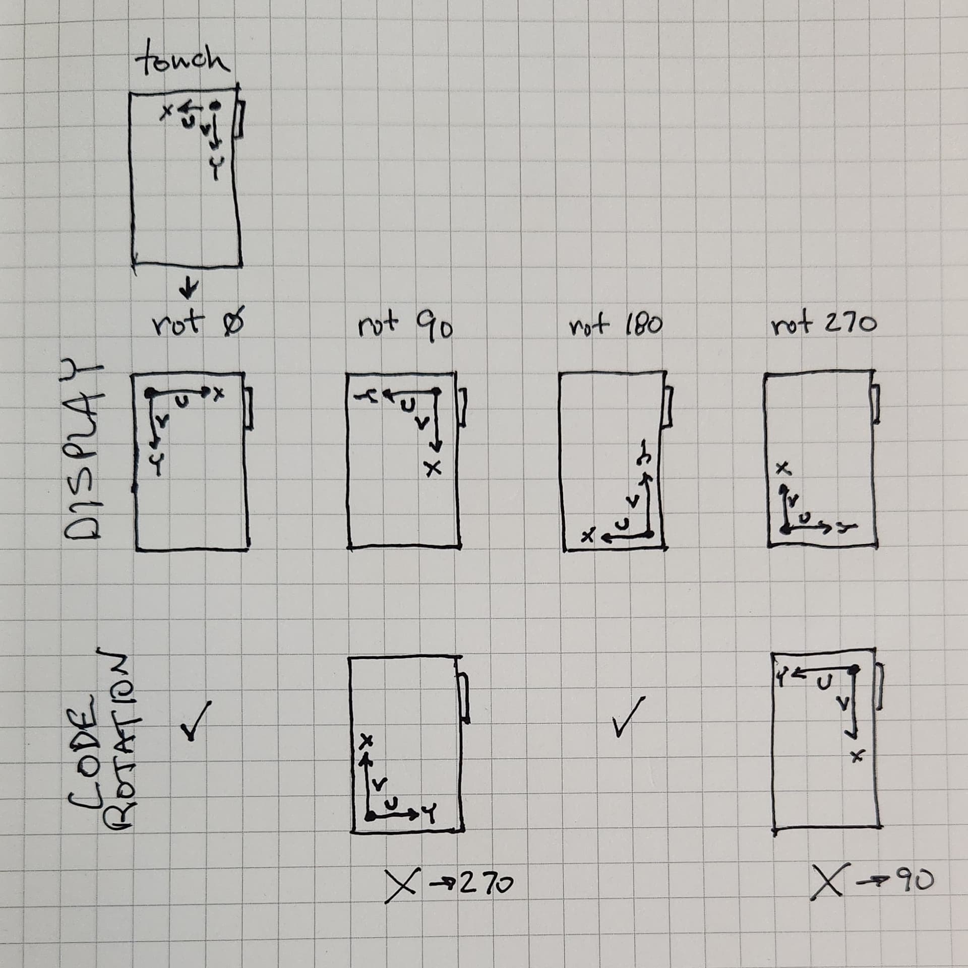
My input device callback returns touchscreen coordinates that work for the rotation 0 and 180 degree cases. For the 90 and 270 degree cases I’m seeing that lv_indev.c:indev_pointer_proc() is rotating those coordinates in the opposite direction from the rotation applied to the display. This, of course, causes a disconnect between the touchscreen and the display. I’ve been able to compensate for and counteract the ‘errant’ rotation in those two cases to obtain correct results. But I’m interested in understanding why this is happening as it may indicate a more serious problem.

What MCU/Processor/Board and compiler are you using?

VS Code
PlatformIO
platform = espressif32
board = adafruit_feather_esp32_v2
framework = arduino
Adafruit TFT FeatherWing

  • 2.4" 320x240 ILI9341 display
  • STMPE811 touchscreen controller

What LVGL version are you using?

lvgl/lvgl @ 9.2.2
Bodmer/TFT_eSPI @ 2.5.43

What do you want to achieve?

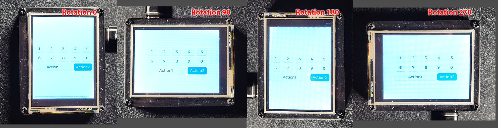
My touch input read callback returns valid coordinates for rotation 0 that work fine. It’s my understanding that LVGL should rotate these properly to match other display rotations. I’m having to compensate for the rotation that will be applied for the 90 and 270 (landscape) cases as it seems to rotate the wrong direction. I’d like to understand why. Perhaps TFT_eSPI isn’t applying the proper display rotation? But that relationship lies in its ties within the LVGL library. Perhaps there’s some additional configuration setting I’m missing to sync these up?

What have you tried so far?

Calibration is fine.
Compensating for the ‘errant’ rotation has it working, but is there an underlying unknown issue?

Code to reproduce

This is the code for the input device callback:

/*Read the touchpad*/
void my_touchpad_read( lv_indev_t * indev, lv_indev_data_t * data )
{
    lv_display_t * disp = lv_indev_get_display(indev);
    // active rotation
    auto rot = lv_display_get_rotation(disp);
    // res changes with rotation
    auto hor_res = lv_display_get_horizontal_resolution(disp);
    auto ver_res = lv_display_get_vertical_resolution(disp);

    bool touched = !ts.bufferEmpty();
    if(!touched)
    {
        data->state = LV_INDEV_STATE_RELEASED;
        if (!wasPressed)
            return;
        wasPressed = false;
    }
    else
    {
        TS_Point p = ts.getPoint();


        /*
        TFT_WIDTH and TFT_HEIGHT are the default portrait dimensions, 240x320
        When the USB port is at top right, portrait, the TS origin is at top right,
        with X left along the short side and Y down along the long side.
        Scale input TS coordintes using the calibration #'s.

        NOTE:
        The LV_DISPLAY_ROTATION_0 case is apparently the coordinate system we should use
        for the return coordinates.
        
        Here is the transform LVGL applies to the coordinates in lv_indev.c:indev_pointer_proc() after
        calling us:
        
            if(disp->rotation == LV_DISPLAY_ROTATION_180 || disp->rotation == LV_DISPLAY_ROTATION_270) {
                data->point.x = disp->hor_res - data->point.x - 1;
                data->point.y = disp->ver_res - data->point.y - 1;
                }
            if(disp->rotation == LV_DISPLAY_ROTATION_90 || disp->rotation == LV_DISPLAY_ROTATION_270) {
                int32_t tmp = data->point.y;
                data->point.y = data->point.x;
                data->point.x = disp->ver_res - tmp - 1;
                }

        The second part rotates the touch point 90 degrees, but in the opposite direction from the display.
        Either this LVGL rotation or what's being done in TGT_eSPI to rotate the display must be 'wrong'.
        */

        int16_t x = 0, y = 0;
        switch (rot)
        {
        case LV_DISPLAY_ROTATION_0:     // portrait (USB top right)
        case LV_DISPLAY_ROTATION_180:   // portrait (USB bottom left)
            // flip the X axis for conversion from the TS system to the ROT_0 system
            // this works for the ROT_180 case too (without the 'wrong' 90 degree rotation)
            x = map(p.x, calib[0], calib[1], TFT_WIDTH-1, 0);
            y = map(p.y, calib[2], calib[3], 0, TFT_HEIGHT-1);
            break;
        
        case LV_DISPLAY_ROTATION_90:    // landscape (USB top left)
        case LV_DISPLAY_ROTATION_270:   // landscape (USB bottom right)
            // this compensates for the 'wrong' 90 degree rotation
            x = map(p.x, calib[0], calib[1], 0, TFT_WIDTH-1);
            y = map(p.y, calib[2], calib[3], TFT_HEIGHT-1, 0);
            break;

        default:
            Serial.print("ROT NOT IMPLEMENTED");
            break;
        }
        data->state = LV_INDEV_STATE_PRESSED;
        data->point.x = constrain(x, 0, TFT_WIDTH-1);
        data->point.y = constrain(y, 0, TFT_HEIGHT-1);
        wasPressed = true;
    }

    Serial.print("rot: ");
    Serial.print(rot);
    Serial.print(" [");
    Serial.print(hor_res);
    Serial.print("x");
    Serial.print(ver_res);
    Serial.print("] ");
    Serial.print("{");
    Serial.print(data->point.x); Serial.print(",");
    Serial.print(data->point.y);
    Serial.print("} ");
    Serial.println(data->state);
}

I do not know how the bodmer drivers are set up. I thought they are done as swap xy, mirror x and mirror y. if they are what functions are you calling and with what parameters for the different rotations?

Most people think it is the touch that is the problem when it is actually the display rotation that is. It all depends on the display as to how it rotates.

I can tell you that there is an error in the logic of your code. rotate 90 and rotate 270 are going to have the x and y axis’s swapped and you are mapping the axis’s to macros for the display width and height which are not swapped this is going to cause an issue near the edges.

180 and 270 degrees have the x and y axis’s mirrored and 270 degrees also swaps the axis. It looks like this


x_min = 0
x_max = 500
y_min = 0
y_max = 500

90°
x_min = 0
x_max = 500
y_min = 0
y_max = 500
x, y = y, x

180°
x_min = 500
x_max = 0
y_min = 500
y_max = 0

270°
x_min = 500
x_max = 0
y_min = 500
y_max = 0

x, y = y, x

That gives a rotation in clockwise direction.

Most display drivers provide 2 functions that handle the rotation. One is swap_xy(true/false) and the other is mirror(x=true/false, y=true/false)


swap_xy(false)
mirror(x=false, y=false)

90°
swap_xy(true)
mirror(x=false, y=false)

180°
swap_xy(false)
mirror(x=true, y=true)

270°
swap_xy(true)
mirror(x=true, y=true)

The code I show is what I’ve had to do to make things work. (And it DOES work.) I should only have to do the mapping in the 0 case (no switch) and let LVGL rotate the coords for the other cases. But the code in lv_indev.c:indev_pointer_proc() rotates my touch coordinates 90 degrees in the ‘wrong’ direction for the 90 and 270 cases. The ‘error’ in my code for those cases adds a 180 rotation to compensate for this ‘wrong’ rotation. (The appropriate snippet from lv_indev.c:indev_pointer_proc() is included in a comment in my code for reference.)

Your comment about the bodmer driver is more interesting. My only code interaction with the display is to define ILI9341 and the pinouts (in platformio.ini) and to set LV_USE_TFT_ESPI in lv_config.h and to create the display device:

disp = lv_tft_espi_create(TFT_WIDTH, TFT_HEIGHT, draw_buf, sizeof(draw_buf));

I have not explored in the code what happens after that between LVGL and TFT_eSPI, but it seems to work for the examples I’ve seen. My display draws fine, but its rotation direction is the opposite of the touch coord roation. But perhaps there are additional TFT_eSPI options for the display that change it’s rotation direction while still drawing properly?


This is a sketch I’ve made to help me understand the coordinate transformations involved. (The little notch on the display rectangle shows where my USB port connector is on the Feather ESP32 board, for positional reference.) The top row shows the touchscreen coordinates. Oddly enough, it has the X axis reversed, but that’s handled easily enough in the map function that also scales against the calibration values. That’s all I need to do to provide good and working touch coordinates for rotation 0, a portrait mode.

The second row shows the display coordinates I get from the 4 display rotation values. I’ve yet to find anything in the LVGL documents that actually describes what coordinate systems and axes to expect for the various rotations. So I can’t tell other than empirically if these rotations should be clockwise or counterclockwise.

The third row shows my understanding of what the coordinates look like after the rotation applied in lv_indev.c:indev_pointer_proc(). This has rotated the coordinates 90 degrees the ‘wrong’ way such that rotation 90 results in what I would expect for 270 and rotation 270 results in what I would expect for 90. (0 and 180 do not get the added 90 rotation treatment.)

Again, my code corrects for this to make it all work out in the end. I’m just trying to understand how this apparently works out-of-the-box for so many, but not for me!

OK do me one favor. forget about the touch coordinates. Put them out of your mind for the moment.

your display with 0 rotation, the orientation is portrait correct? If that is the case then your resolution is NOT 320 x 240 it is 240 x 320. That’s for starters. In your original post you state the resolution is 320 x 240. I want to make sure that we are starting off with everything how it should be. When you call lv_display_create you should be calling it as lv_display_create(240, 320) I want to make sure we are both on the same page.

We need to nail down what way the display needs to be held when no rotation is applied. You may not be setting the rotation, it could be getting set in the hardware display driver init sequence without you being aware of that happening. You say the display is an ILI9341. For that display IC there is a setting called “MADCTL” to access it 0x0B is the command and there is a single byte sent as data and that single byte breaks down to the bit level as follows.

bit 7: mirror y
       0: Top to Bottom.
       1: Bottom to Top.

bit 6: mirror X
       0: Left to Right
       1: Right to Left

bit 5: x, y = y, x
       0: Normal Mode
       1: Reverse Mode

bit 4: Doesn't apply to the rotation so set it to 0
       0: LCD Refresh Top to Bottom
       1: LCD Refresh Bottom to Top

bit 3: 0: RGB
       1: BGR

bit 2: Doesn't apply to the rotation so set it to 0
       0: LCD Refresh Left to Right
       1: LCD Refresh Right to Left

bit 1: Always set to 0

bit 0: Always set to 0

I am sure there is a way for you to send a command and parameters to the display using TFT_eSPI. find out how to do that and send command 0x0B with the single byte parameter as 0x00 Then have LVGL render a GUI. The way the display is seen is it’s native orientation and this would be 0° rotation.

When you do this there is a possibility of the test either being mirrored on the X axis or on the Y axis or on both.

We need to nail down what exactly is the native orientation where the UI is able to be displayed correctly using the native resolution of 240 x 320. what you believe to be a rotation of zero might not be at the hardware level. According to the data sheet a rotation of 0 is when that parameter is set to 0x00. If the UI gets displayed incorrectly that can happen because of how the frame buffer is being sent to the display. if the display IC is expecting the last byte of the buffer to be sent first but instead the first byte is being sent first then you will end up with the image being mirrored and to correct that one of the settings is being altered in the init command and that setting being altered from the get go could be altering the direction of the rotation.

How LVGL alters the touch coordinates when rotating is clockwise.

You mentioned your x axis on the touch being backwards for rotation 0. This is a simple thing to fix and it is caused by the touch IC not being connected to the touch panel correctly. It is very annoying when display manufacturers do this and I have seen it many times. to correct it all you need to do is have the following code in your indev callback

data->point.x = TFT_WIDTH - 1 - p.x;

You do not need to use map to fix the issue. It’s simple math to make the adjustment.

You should only need to check and see if there is a touch and if there is set the state to PRESSED and set the x coordinate for data as seen above and set the y coordinate to exactly what has been received. If there is no touch then set the state to RELEASED. That’s all that you should need to do.

When you rotate the display there are things you need to do and one of them is telling LVGL to perform the rotate and the others are setting the mirror and swap xy for the hardware display driver. If the touch doesn’t align properly with what is being displayed the problem is not in the touch, it’s with the hardware display driver settings. You need to adjust the swap XY and mirror values until what is being displayed aligns with the touch.

You have to trust me with this. I have seen it many many many times. The readability of how it is being done is not the best that’s for sure and trust me it has been brought up.

Here is something you can also read which will help to get a better grasp on what is actually taking place. The current code in LVGL does the math so the coordinates do come out correct. Not the easiest on the eyes but it does work correctly. I had to get out the paper and pencil to do the math in order to figure out what was going on in the code. Once I figured out that the code was in fact correct in LVGL is when I discovered the problem to be in that MADCTL config for the display I was using.

@kisvegabor


Ok, there’s a lot to unpack here, so one thing at a time. Forgetting about touch coordinates, as you request. This image shows my display for the 4 rotation values. You can see the USB connection to understand the device orientation.

  1. Are these the expected visual results?
  2. Is the origin (0,0) always at the top left with the X axis increasing to the right and the Y axis increasing downward?

OK it is rotating properly. the UI is rotating clockwise which would mean you have to turn the device counter clockwise to view it correctly. So that is functioning properly…

0, 0 as per LVGL it always the top left… When you have the rotation set to zero and you touch the screen in the upper left corner the raw coordinates should be at 0, 0 or there abouts. If they are not we need to make them that way before passing those coordinates to LVGL. If you get the coordinates for the touch to be at 0, 0 with zero rotation and touching the upper left corner then everything else should fall into place at this point.

Now you had said in one of your previous posts that the X axis is backwards. meaning 0 for x axis for the touch is in the upper right corner. y axis is fine. If that is the case then a simple flip of the x axis to move the zero position to the left should take care of the issues.

The touch IC you are using is resistive which means you MUST perform a calibration. This is due to alignment of the touch screen to the display but also the resolution of the touch screen might not be match with the display. This would cause the touch to not work as it should.

I wrote a touch screen calibration routine that is probably one of the most accurate that has been written. It not only maps the coordinates correctly but it creates a transform matrix to handle the touch screen being attached to the display at an angle. It also handles reversed axis and things of that nature as well.

It is written in Python code but I can port the logic of it to C code which will allow you to simply feed in the expected coordinates and the actual coordinates for 3 points/touches and it will give you back the calibration numbers. You can store those numbers in NVS on the ESP32 or you can have them hard coded into your program.

I kind of slapped this together really fast. There could be some screw ups in it that will need to be fixed…

// ********************************************
// touch_calibration.h
// ********************************************

#include <stdint.h>

#ifndef __TOUCH_CALIBRATION_H__
    #define __TOUCH_CALIBRATION_H__
    
    typedef struct {
        union {
            struct {
                float f_alphaX;
                float f_betaX;
                float f_deltaX;
                float f_alphaY;
                float f_betaY;
                float f_deltaY;
            };
            struct {
                uint32_t i_alphaX; 
                uint32_t i_betaX; 
                uint32_t i_deltaX; 
                uint32_t i_alphaY; 
                uint32_t i_betaY; 
                uint32_t i_deltaY;
        };
    } touch_calibration_data_t;
    
    typedef struct {
        int32_t x;
        int32_t y;
    } point_t;
    
    typedef struct {
        point_t target;
        point_t actual;
    } touch_calibration_point_t;
    

#endif /* __TOUCH_CALIBRATION_H__ */


// ********************************************
// touch_calibration.c
// ********************************************

#include <stdint.h>
#include "touch_calibration.h"


void calibrate(int32_t *x, int32_t *y, touch_calibration_data_t *cal_data) 
{
    *x = (int32_t)((float)((*)x) * cal_data->f_alphaX + (float)((*)y) * cal_data->f_betaX + cal_data->f_deltaX);
    *y = (int32_t)((float)((*)x) * cal_data->f_alphaY + (float)((*)y) * cal_data->f_betaY + cal_data->f_deltaY);
}


void calculate_calibration(touch_calibration_point_t points[3], touch_calibration_data_t *cal_data)
{

        float divisor = (float)(
            points[0].actual.x * (points[2].actual.y - points[1].actual.y) - points[1].actual.x * points[2].actual.y + 
            points[1].actual.y * points[2].actual.x + points[0].actual.y * (points[1].actual.x - points[2].actual.x)
        );
       
        cal_data->f_alphaX = (float)(
            points[0].target.x * (points[2].actual.y - points[1].actual.y) - points[1].target.x * points[2].actual.y + 
            points[2].target.x * points[1].actual.y + (points[1].target.x - points[2].target.x) * points[0].actual.y
        ) / divisor;
        
        cal_data->f_betaX = -(float)(
            points[0].target.x * (points[2].actual.x - points[1].actual.x) - points[1].target.x * points[2].actual.x + 
            points[2].target.x * points[1].actual.x + (points[1].target.x - points[2].target.x) * points[0].actual.x
        ) / divisor;
        
        cal_data->f_deltaX = (float)(
            points[0].target.x * (points[1].actual.y * points[2].actual.x - points[1].actual.x * points[2].actual.y) + 
            points[0].actual.x * (points[1].target.x * points[2].actual.y - points[2].target.x * points[1].actual.y) + 
            points[0].actual.y * (points[2].target.x * points[1].actual.x - points[1].target.x * points[2].actual.x)
        ) / divisor;
        
        cal_data->f_alphaY = (float)(
            points[0].target.y * (points[2].actual.y - points[1].actual.y) - points[1].target.y * points[2].actual.y + 
            points[2].target.y * points[1].actual.y + (points[1].target.y - points[2].target.y) * points[0].actual.y
        ) / divisor
        
        cal_data->f_betaY = -(float)(
            points[0].target.y * (points[2].actual.x - points[1].actual.x) - points[1].target.y * points[2].actual.x +
            points[2].target.y * points[1].actual.x + (points[1].target.y - points[2].target.y) * points[0].actual.x
        ) / divisor;
        
        cal_data->f_deltaY = (float)(
            points[0].target.y * (points[1].actual.y * points[2].actual.x - points[1].actual.x * points[2].actual.y) +
            points[0].actual.x * (points[1].target.y * points[2].actual.y - points[2].target.y * points[1].actual.y) +
            points[0].actual.y * (points[2].target.y * points[1].actual.x - points[1].target.y * points[2].actual.x)
        ) / divisor;
}


/*
 INSTRUCTIONS:
 
 create the LVGL indev driver and pause it
 
 create a UI for doing the touch calibration. This UI should be a blank screen 
 with only 2 widgets on it. Those 2 widgets are the line widget. You want to make
 a cross with the 2 lines. You will position the cross in the upper left corner
 where the center of the cross is at 30, 30. once you create the cross call 'lv_refr_now'
 
 the 3 points you will want to position like so.
 
 point 1 upper left
 point 2 upper right
 point 3 lower left
 
   |                                                    |
 -----                                                -----
   |                                                    |


   |
 -----
   |
  
  
 after you call `lv_refr_now` you will want code similiar to the folowing
 
 '''
 bool calibration_running = True;

 touch_calibration_point_t cal_points[3] = {
    { .target={ .x=30, .y=30 } },
    { .target={ .x=TFT_WIDTH - 1 - 30, .y=30 } },
    { .target={ .x=30, .y=TFT_HEIGHT - 1 - 30 } },
 };
 
 lv_indev_data_t indev_data = { .state = LV_INDEV_STATE_RELEASED };
 
 
 for (int i=0; i<3; i++) { 
    indev_data.point.x = 0;
    indev_data.point.y = 0;
    indev_data.state = LV_INDEV_STATE_RELEASED;
    
    // move the 2 line widgets using the coordinates from cal_points[i].target
    
    lv_refr_now();
     
    while (indev_data.state == LV_INDEV_STATE_RELEASED) {
        indev_callback_func(NULL, &indev_data);
    }
 
    cal_points[i].actual.x = indev_data.point.x;
    cal_points[i].actual.y = indev_data.point.y;
 }
 
 touch_calibration_data_t calibration_data;
 calculate_calibration(cal_points, &calibration_data);   
 '''
 
 and now you have the calibration data stored in `calibration_data`. 
 If you look at the `touch_calibration_data_t` structure you will notice it is 
 nested with a union and a couple of structures. There is a method to my madness.
 The ESP32 NVS is not able to deal with floats but you can store unsigned integers.
 Since a float is 4 bytes and a uint32_t is 4 bytes we can get an exact bit 
 representation of the float as a uint32_t by using a union. 
 The values you would store in the NVS are the fields that start with "i_" and those 
 same fields you would fill with the values that are saved in the NVS.
 
 You will need to read up on how to access the NVS and how to create an NVS partition. 
 Doing this is going to be different using the Arduino IDE than it would be if you were 
 using the ESP-IDF build system. That is something you will need to figure out. I will 
 help as much as I can with it but I am really not all that familiar with the 
 ESP32 SDK API for the Arduino IDE.
 
 
 OH and don't forget to unpause the LVGL indev driver after you have finished doing the calibration.


To use the calibration do the following from inside of your indev callback function

'''


void indev_cb(lv_indev_t *indev, lv_indev_data_t *data)
{

    // code to get touch points;

    if (points) {
        if (!calibration_running) {
            calibrate(&p.x, &p.y, &calibration_data);
        }

        data->point.x = p.x;
        data->point.y = p.y;
        data->state = LV_INDEV_STATE_PRESSED;
    } else {
        data->state = LV_INDEV_STATE_RELEASED;
    }
}
'''
 */

OK it is rotating properly. the UI is rotating clockwise which would mean you have to turn the device counter clockwise to view it correctly. So that is functioning properly…

0, 0 as per LVGL it always the top left… When you have the rotation set to zero and you touch the screen in the upper left corner the raw coordinates should be at 0, 0 or there abouts. If they are not we need to make them that way before passing those coordinates to LVGL. If you get the coordinates for the touch to be at 0, 0 with zero rotation and touching the upper left corner then everything else should fall into place at this point.

OK, let’s ignore my implementation of the indev read callback for this step and assume a perfect one. Then follow a simple pair of touch coordinates through the pipeline. A touch on the lower left corner of the display in rotation 90 is equivalent to a touch on the upper left corner of rotation 0. As you say, that’s touch point (0,0) which is the value that should be returned by the perfect implementation.

Here is the transform LVGL applies to the coordinates in lv_indev.c:indev_pointer_proc() after calling us:

if(disp->rotation == LV_DISPLAY_ROTATION_180 || disp->rotation == LV_DISPLAY_ROTATION_270) {
  data->point.x = disp->hor_res - data->point.x - 1;
  data->point.y = disp->ver_res - data->point.y - 1;
  }
if(disp->rotation == LV_DISPLAY_ROTATION_90 || disp->rotation == LV_DISPLAY_ROTATION_270) {
  int32_t tmp = data->point.y;
  data->point.y = data->point.x;
  data->point.x = disp->ver_res - tmp - 1;
  }

The second part is the rotation 90 case. That will take the (0,0) TS point and change it to (319,0) in display coordinates. But that is the upper right point of the rotation 90 display! It should be (0,239), the lower left point of the display. I can’t help but think this is wrong! It looks to me like that’s a -90 rotation. This follows my earlier analysis as shown in the sketch in my 2nd post. The CODE ROTATION for 90 (3rd row, 2nd column) results in what we should expect for the 270 DISPLAY rotation (2nd row, 4th column).

what this code is doing is rather crazy.

if(disp->rotation == LV_DISPLAY_ROTATION_180 || disp->rotation == LV_DISPLAY_ROTATION_270) {
  data->point.x = disp->hor_res - data->point.x - 1;
  data->point.y = disp->ver_res - data->point.y - 1;
  }
if(disp->rotation == LV_DISPLAY_ROTATION_90 || disp->rotation == LV_DISPLAY_ROTATION_270) {
  int32_t tmp = data->point.y;
  data->point.y = data->point.x;
  data->point.x = disp->ver_res - tmp - 1;
  }

let me explain.

lets say your indev coordinates are correct for rotation zero. when you rotate 90° LVGL does 2 things. The first thing it does is it flip flips the width and height that is set in lv_display_t, width, height = height, width. The second thing that happens is the coordinates for the touch input get modified so they will translate to the proper coordinates.

with a 90° degree rotation this is the code that runs in LVGL for the altering of the coordinates…

int32_t tmp = data->point.y;
  data->point.y = data->point.x;
  data->point.x = disp->ver_res - tmp - 1;

it is flipping the x and y axis that has been passed in. and it is reversing the x axis so instead of it being 0 - 240 it is set at 240 - 0. Now remember the x axis as far as the touch input is concerned is actually the Y axis in the UI. Think about the direction the UI rotate and not the direction you need to rotate the device to view it correctly. with a 90 degree rotation the x axis left to right becomes the UI’s y axis bottom to top which is the reason why it needs to be flipped is because it needs to be top to bottom.

image

see how the touch x axis arrow is pointing the opposite direction of the UI Y axis??

Here are the translations for the 4 corners of the touch input.

0, 0 touch → 0, 239 UI
239, 0 touch → 0, 0 UI
0, 319 touch → 319, 239 UI
239, 319 touch → 319, 0 UI

You are going through the same thing I did when I saw that touch code. It is really not the easiest bit of code to read to be able to understand what is happening.

Here is the code keyed out in an easier to understand way.

I think I got this right…

switch(disp->rotation) {
    case LV_DISPLAY_ROTATION_0:
        // do nothing
        break;

    case LV_DISPLAY_ROTATION_90:
        // swap xy
        int32_t tmp_y = data->point.y;
        data->point.y = data->point.x;
        data->point.x = tmp_y;

        // remember that disp->hor_res, disp->ver_res = disp->ver_res, disp->hor_res
        // disp->ver_res == 240
        data->point.x = disp->ver_res - data->point.x - 1;
        break;

    case LV_DISPLAY_ROTATION_180:
        data->point.x = disp->hor_res - data->point.x - 1;
        data->point.y = disp->ver_res - data->point.y - 1;
        break;

    case LV_DISPLAY_ROTATION_270:
        // swap xy
        int32_t tmp_x = data->point.x;
        data->point.x = data->point.y;
        data->point.y = tmp_x;

        // remember that disp->hor_res, disp->ver_res = disp->ver_res, disp->hor_res
        // disp->hor_res == 320
        data->point.y = disp->hor_res - data->point.y - 1;
        break;
}

Well, this is fun! :wink:

0, 0 touch → 0, 239 UI

I don’t follow your result in the code at all! For TS coords (0,0), let’s go through it step by step:

int32_t tmp = data->point.y;

tmp <= 0

data->point.y = data->point.x;

data->point.y <= 0

data->point.x = disp->ver_res - tmp - 1;

data->point.x <= 320 - 0 - 1
data->point.x <= 319
(data->point.x,data->point.y) <= (319,0)

You have the wrong coordinate order and the wrong ver_res value.

Note that disp->ver_res is actually 320 (NOT 240!) as these fields appear to always contain the rotation 0 dimensions. I verified this with the trace output in my original code as shown in the 1st post. It shows 320x240 in rotation 90. You can see the resolution values being adjusted for rotation in lv_display.c:

int32_t lv_display_get_horizontal_resolution(const lv_display_t * disp)
{
    if(disp == NULL) disp = lv_display_get_default();

    if(disp == NULL) {
        return 0;
    }
    else {
        switch(disp->rotation) {
            case LV_DISPLAY_ROTATION_90:
            case LV_DISPLAY_ROTATION_270:
                return disp->ver_res;
            default:
                return disp->hor_res;
        }
    }
}

int32_t lv_display_get_vertical_resolution(const lv_display_t * disp)
{
    if(disp == NULL) disp = lv_display_get_default();

    if(disp == NULL) {
        return 0;
    }
    else {
        switch(disp->rotation) {
            case LV_DISPLAY_ROTATION_90:
            case LV_DISPLAY_ROTATION_270:
                return disp->hor_res;
            default:
                return disp->ver_res;
        }
    }
}

These functions return values swapped as necessary to represent the dimensions of the current rotation. So the internal values must be the rotation 0 values. That makes sense as you would not want to invert the X axis using a vertical resolution. And YES, that must be VERY confusing to those working on the library internals!

OK… every single image you have shown for the display is the layout being portrait. That would mean that the width is 240 and the height is 320. when you rotate the display 90 degrees the width ends up being 320 and the height ends up being 240. when you call lv_display_set_rotation it flip flops the width and the height if the rotation is 90° or 270°. so when the code runs that modifies the x, y touch coordinates it needs to make the touch input work in the ranges of the vertical resolution and the horizontal resolution of the display… the vertical and horizontal resolutions are set depending on the display orientation.

Lets do the easy thing here…

Here is a display that is 8 x 12. you press the touchscreen at the coordinates x=5, y=9

image

Now you have the display rotated 90 degrees and you press the screen in the exact same place

image

The coordinates the touch screen transmits are the exact same as they were when rotation was 0°. The touch screen is not orientation aware

Now lets use the code in LVGL and see what we come up with for a result.

I just noticed that these 2 values do not flip flop like I thought they did. I could have sworn that is how LVGL did it in the past. I am going to have to look and see if any changes were made to the code.

hor_res = 8
ver_res = 12

touch x = 5
touch y = 9

if(disp->rotation == LV_DISPLAY_ROTATION_180 || disp->rotation == LV_DISPLAY_ROTATION_270) {
  data->point.x = disp->hor_res - data->point.x - 1;
  data->point.y = disp->ver_res - data->point.y - 1;
  }
if(disp->rotation == LV_DISPLAY_ROTATION_90 || disp->rotation == LV_DISPLAY_ROTATION_270) {
  int32_t tmp = data->point.y;

  tmp = 9

  data->point.y = data->point.x;

  data->point.y = 5
  
  data->point.x = disp->ver_res - tmp - 1;

 data->point.x = 12 - 9 - 1;

data->point.x = 2
  }

so the coordinates were converted to x=2 y=5… what was it that they needed to be for rotation 90?. they needed to be 2, 5 which is exactly what they are.

the real brain twister is rotation 270°

hor_res = 8
ver_res = 12

touch x = 5
touch y = 9

if(disp->rotation == LV_DISPLAY_ROTATION_180 || disp->rotation == LV_DISPLAY_ROTATION_270) {

  data->point.x = disp->hor_res - data->point.x - 1;
  data->point.x = 8 - 5 - 1
  data->point.x = 2

  data->point.y = disp->ver_res - data->point.y - 1;
  data->point.y =  12 - 9 - 1
  data->point.y = = 2
  }

if(disp->rotation == LV_DISPLAY_ROTATION_90 || disp->rotation == LV_DISPLAY_ROTATION_270) {
  int32_t tmp = data->point.y;
  tmp = 2

  data->point.y = data->point.x;
  data->point.y = 2
  
  data->point.x = disp->ver_res - tmp - 1;
  data->point.x = 12 - 2 - 1;
  data->point.x = 9
  }

x = 9, y = 2

and those coordinates do map correctly

image

OK… every single image you have shown for the display is the layout being portrait.

Not exactly. In the earlier sketch I have indeed shown the device always in the canonical TS rotation 0 portrait attitude with the display axes redrawn to reflect the rotation of the display on the device for each case. The origin moves one corner to the next clockwise with each rotation of the display, as it should. The photo collage shows the device rotated so that each display rotation is viewed properly upright. You agreed that represents the expected visual behavior for display rotation. Logically, you can think of the rotation as either the display rotating right or the device rotating left.

Lets do the easy thing here…

If by easy you mean more complicated or incorrect, then let’s do it! I assert you’ve rotated the device along with the display here. This is why I like to picture this stuff with the the device locked and just the display rotating. So take your first rectangle, leave it portrait and just visually/mentally rotate only the display. Cock your head to visualize if you have to. The display pixels then all become Y==0 on the long right edge. The TS coordinate values stay at Y==0 along the short top edge. Now you can rotate the device rectangle to the left, physically, not mathematically, to better visualize the result relative to the display. Now the left most pixels should be TS x==0. They are not, in your diagram! Your labels show them on the right, 180 degrees off.

Your green TS point should then be at (9,2) near the upper right of the display and not the (2,5) near the lower left as the transform yields. That is 180 degrees wrong. I assert your 90 degree final rectangle and your 270 degree final rectangle should be swapped. That is exactly the behavior I’m seeing, and why my indev callback requires a 180 degree rotation to compensate for these two landscape cases.

The easy ‘thing’ here would actually be to go back to the analysis in my previous post following the simpler numbers of TS (0,0) through the transform and identifying a mistake. I still don’t see it.

hi…
did you solve it?
I read the whole discussion and I would like to ask you first if I understood your problem related to the rotation.

  1. ) do you use the TFT_eSPI library Ver. 2.5.43 by Bodmer?
    2.) do you use the routines included in TFT_eSPI to read the touchpad?
    3.) do you use the “lv_tft_espi_create” function to create a display?

If so, then there is a simpler and more linear solution to solve the rotation problem.

if so, let me know

@Driver55

  • TFT_eSPI latest version.
  • Not using any TS read routines in TFT_eSPI.
  • Yes, using lv_tft_espi_create, as stated.

As stated in my original post, I had already “solved” the problem but was just trying to understand the disconnect between the display rotation and the TS coord rotation. Especially as I’d seen it in three different displays! In a later post here with pictures of my display at the 4 rotations I asked, Are these the expected visual results? Unfortunately, I got the wrong answer! This took the discussion along an unproductive path. So I asked the question as an LVGL GitHub issue and got the definitive answer that my display was rotating in the wrong direction. Which doesn’t explain why LVGL’s own TFT_eSPI functionality does the wrong thing. Better documentation, i.e. anything at all about what it means to rotate the display, would have exposed this problem at the start. But poor documentation is as common as the cold. Once down and back out of the rabbit hole, my workaround in the TS input device callback (adjust the values in the 90 & 270 cases with an additional 180 rotation) seems about as simple as anything possible. But I’m always up for learning new tricks if you think you have a simpler approach.

I see that you do not have the same configuration, but I think it can help you to understand better the problem
Take a look here: