Esp32 second 8 bit interface display

Description

What MCU/Processor/Board and compiler are you using?

esp32s3

What LVGL version are you using?

8

What do you want to achieve?

2 same displays 240х280 showing splitted picture

Code to reproduce

Add a code snippet which can run in the simulator. It should contain only the relevant code that compiles without errors when separated from your main code base.

The code block(s) should be formatted like:

/*You code here*/
#include <stdio.h>
#include "freertos/FreeRTOS.h"
#include "freertos/task.h"
#include "esp_timer.h"
#include "esp_lcd_panel_io.h"
#include "esp_lcd_panel_vendor.h"
#include "esp_lcd_panel_ops.h"
#include "driver/gpio.h"
#include "esp_err.h"
#include "esp_log.h"
#include "lvgl.h"

static const char *TAG = "example";


#define EXAMPLE_LCD_PIXEL_CLOCK_HZ     (10 * 1000 * 1000)
#define EXAMPLE_LCD_BK_LIGHT_ON_LEVEL  1
#define EXAMPLE_LCD_BK_LIGHT_OFF_LEVEL !EXAMPLE_LCD_BK_LIGHT_ON_LEVEL
#define EXAMPLE_PIN_NUM_DATA0          8
#define EXAMPLE_PIN_NUM_DATA1          3
#define EXAMPLE_PIN_NUM_DATA2          9
#define EXAMPLE_PIN_NUM_DATA3          10
#define EXAMPLE_PIN_NUM_DATA4          11
#define EXAMPLE_PIN_NUM_DATA5          12
#define EXAMPLE_PIN_NUM_DATA6          13
#define EXAMPLE_PIN_NUM_DATA7          14
#define EXAMPLE_PIN_NUM_PCLK           18
#define EXAMPLE_PIN_NUM_CS             15
#define EXAMPLE_PIN_NUM_DC             16
#define EXAMPLE_PIN_NUM_RST            17
#define EXAMPLE_PIN_NUM_BK_LIGHT       2

// The pixel number in horizontal and vertical
#define EXAMPLE_LCD_H_RES              240
#define EXAMPLE_LCD_V_RES              280
// Bit number used to represent command and parameter
#define EXAMPLE_LCD_CMD_BITS           8
#define EXAMPLE_LCD_PARAM_BITS         8

#define EXAMPLE_LVGL_TICK_PERIOD_MS    2

extern void example_lvgl_demo_ui(lv_obj_t *scr);

static bool example_notify_lvgl_flush_ready(esp_lcd_panel_io_handle_t panel_io, esp_lcd_panel_io_event_data_t *edata, void *user_ctx)
{
    lv_disp_drv_t *disp_driver = (lv_disp_drv_t *)user_ctx;
    lv_disp_flush_ready(disp_driver);
    return false;
}

static void example_lvgl_flush_cb(lv_disp_drv_t *drv, const lv_area_t *area, lv_color_t *color_map)
{
    esp_lcd_panel_handle_t panel_handle = (esp_lcd_panel_handle_t) drv->user_data;
    int offsetx1 = area->x1;
    int offsetx2 = area->x2;
    int offsety1 = area->y1;
    int offsety2 = area->y2;
    // copy a buffer's content to a specific area of the display
    esp_lcd_panel_draw_bitmap(panel_handle, offsetx1, offsety1, offsetx2 + 1, offsety2 + 1, color_map);
}

static void example_increase_lvgl_tick(void *arg)
{
    /* Tell LVGL how many milliseconds has elapsed */
    lv_tick_inc(EXAMPLE_LVGL_TICK_PERIOD_MS);
}

void app_main(void)
{
    static lv_disp_draw_buf_t disp_buf; // contains internal graphic buffer(s) called draw buffer(s)
    static lv_disp_drv_t disp_drv;      // contains callback functions

    ESP_LOGI(TAG, "Turn off LCD backlight");
    gpio_config_t bk_gpio_config = {
        .mode = GPIO_MODE_OUTPUT,
        .pin_bit_mask = 1ULL << EXAMPLE_PIN_NUM_BK_LIGHT
    };
    ESP_ERROR_CHECK(gpio_config(&bk_gpio_config));
    gpio_set_level(EXAMPLE_PIN_NUM_BK_LIGHT, EXAMPLE_LCD_BK_LIGHT_OFF_LEVEL);

    ESP_LOGI(TAG, "Initialize Intel 8080 bus");
    esp_lcd_i80_bus_handle_t i80_bus = NULL;
    esp_lcd_i80_bus_config_t bus_config = {
        .dc_gpio_num = EXAMPLE_PIN_NUM_DC,
        .wr_gpio_num = EXAMPLE_PIN_NUM_PCLK,
        .data_gpio_nums = {
            EXAMPLE_PIN_NUM_DATA0,
            EXAMPLE_PIN_NUM_DATA1,
            EXAMPLE_PIN_NUM_DATA2,
            EXAMPLE_PIN_NUM_DATA3,
            EXAMPLE_PIN_NUM_DATA4,
            EXAMPLE_PIN_NUM_DATA5,
            EXAMPLE_PIN_NUM_DATA6,
            EXAMPLE_PIN_NUM_DATA7,
        },
        .bus_width = 8,
        .max_transfer_bytes = EXAMPLE_LCD_H_RES * 40 * sizeof(uint16_t)
    };
    ESP_ERROR_CHECK(esp_lcd_new_i80_bus(&bus_config, &i80_bus));
    esp_lcd_panel_io_handle_t io_handle = NULL;
    esp_lcd_panel_io_i80_config_t io_config = {
        .cs_gpio_num = EXAMPLE_PIN_NUM_CS,
        .pclk_hz = EXAMPLE_LCD_PIXEL_CLOCK_HZ,
        .trans_queue_depth = 10,
        .dc_levels = {
            .dc_idle_level = 0,
            .dc_cmd_level = 0,
            .dc_dummy_level = 0,
            .dc_data_level = 1,
        },
        .on_color_trans_done = example_notify_lvgl_flush_ready,
        .user_ctx = &disp_drv,
        .lcd_cmd_bits = EXAMPLE_LCD_CMD_BITS,
        .lcd_param_bits = EXAMPLE_LCD_PARAM_BITS,
    };
    ESP_ERROR_CHECK(esp_lcd_new_panel_io_i80(i80_bus, &io_config, &io_handle));

    ESP_LOGI(TAG, "Install LCD driver of st7789");
    esp_lcd_panel_handle_t panel_handle = NULL;
    esp_lcd_panel_dev_config_t panel_config = {
        .reset_gpio_num = EXAMPLE_PIN_NUM_RST,
        .color_space = ESP_LCD_COLOR_SPACE_RGB,
        .bits_per_pixel = 16,
    };
    ESP_ERROR_CHECK(esp_lcd_new_panel_st7789(io_handle, &panel_config, &panel_handle));

    esp_lcd_panel_reset(panel_handle);
    esp_lcd_panel_init(panel_handle);
    esp_lcd_panel_invert_color(panel_handle, true);
    // the gap is LCD panel specific, even panels with the same driver IC, can have different gap value
    esp_lcd_panel_set_gap(panel_handle, 0, 20);

    ESP_LOGI(TAG, "Turn on LCD backlight");
    gpio_set_level(EXAMPLE_PIN_NUM_BK_LIGHT, EXAMPLE_LCD_BK_LIGHT_ON_LEVEL);

    ESP_LOGI(TAG, "Initialize LVGL library");
    lv_init();
    // alloc draw buffers used by LVGL
    // it's recommended to choose the size of the draw buffer(s) to be at least 1/10 screen sized
    lv_color_t *buf1 = heap_caps_malloc(EXAMPLE_LCD_H_RES * 20 * sizeof(lv_color_t), MALLOC_CAP_DMA);
    assert(buf1);
    lv_color_t *buf2 = heap_caps_malloc(EXAMPLE_LCD_H_RES * 20 * sizeof(lv_color_t), MALLOC_CAP_DMA);
    assert(buf2);
    // initialize LVGL draw buffers
    lv_disp_draw_buf_init(&disp_buf, buf1, buf2, EXAMPLE_LCD_H_RES * 20);

    ESP_LOGI(TAG, "Register display driver to LVGL");
    lv_disp_drv_init(&disp_drv);
    disp_drv.hor_res = EXAMPLE_LCD_H_RES;
    disp_drv.ver_res = EXAMPLE_LCD_V_RES;
    disp_drv.flush_cb = example_lvgl_flush_cb;
    disp_drv.draw_buf = &disp_buf;
    disp_drv.user_data = panel_handle;
    lv_disp_t *disp = lv_disp_drv_register(&disp_drv);

    ESP_LOGI(TAG, "Install LVGL tick timer");
    // Tick interface for LVGL (using esp_timer to generate 2ms periodic event)
    const esp_timer_create_args_t lvgl_tick_timer_args = {
        .callback = &example_increase_lvgl_tick,
        .name = "lvgl_tick"
    };
    esp_timer_handle_t lvgl_tick_timer = NULL;
    ESP_ERROR_CHECK(esp_timer_create(&lvgl_tick_timer_args, &lvgl_tick_timer));
    ESP_ERROR_CHECK(esp_timer_start_periodic(lvgl_tick_timer, EXAMPLE_LVGL_TICK_PERIOD_MS * 1000));

    ESP_LOGI(TAG, "Display LVGL animation");
    lv_obj_t *scr = lv_disp_get_scr_act(disp);
    example_lvgl_demo_ui(scr);

    while (1) {
        // raise the task priority of LVGL and/or reduce the handler period can improve the performance
        vTaskDelay(pdMS_TO_TICKS(10));
        // The task running lv_timer_handler should have lower priority than that running `lv_tick_inc`
        lv_timer_handler();
    }
}

I compiled the example of st7789 display with parallel 8 bit interface. How to modify the program to add 2nd same display? I understand that its neccesary to modify flush callback function changing cs pin and output parts of bitmap area for every display. But I have no idea how to do that exactly. Please assist if possible.
Don’t know if I unterstand you correctly:
You have two identical LCDs each 240x280 (w x h ?) located side by side, so they form a virtual display of size 480 x 280?

Yes! Exactly.

So you setup lvgl with a resolution of 480 x 280 instead of 240 x 280.

Within your flush_cb you have to check the coordinates of area and have to split the data according to which pixel belongs to the left display and which pixel belongs to the right pixel and send the pixels accordingly to the correct display.

))) You repeat my first post almost literally. I know, what I need to modify, but I don’t know how, because I don’t understand how to init the 2nd display and to connect it to driver with separate cs pin.

Maybe you set up a second panel with a second i80 bus handle which references the cs of the second display.

I do not believe that LVGL is set up to handle adding displays together to create what would be a virtual display that has the combined resolutions of both displays. It is able to mirror or have separate displays but not joining them.

I take the liberty of a small contradiction :wink:
LVGL doesn’t know anything about the connected display hardware.
LVGL just needs to know about the width and height and color depth for rendering into a buffer.
How the buffer content is transferred into a real display is not of interest for lvgl.
Transferring the data to the real display hardware is done in the flush callback function.

As I understand, Zheckiss question would be more relevant to be asked in an ESP32 forum.
As how to configure ESP32 to use one 8080 interface for two displays separated by two different CS (chip select) pins.

The flush function then has just to decide which of the area pixel has to be send to which display. And that seems to be more or less easy.

But… if the objects are off the side of the display does LVGL still “render” it. It wouldn’t make sense for it to do that because if you had a display that was 480 x 320 and the “GUI” had a size of 480 x 600 there would be no need for LVGL to render anything outside of the display area.

You also have conditions that exist like if you wanted the displays to be diagonal to each other. so corner to corner. if you plug into the driver for LVGL a display that has a size of 960 x 640 that would actually be incorrect and LVGL would be wasting processor time and memory rendering things that ultimately would not be seen on a display.

I do understand that things are able to be handled in the flush function itself and a user would be able to sort out what goes where. It would be far easier if LVGL handled it internally when the data was being written to the buffer. This way no iteration would need to be done in order to move the data to another buffer so it could be sent.

The other thing you loose out on is using DMA memory to its fullest potential. Because while one buffer is being written you would have to stall the flush callback because of the shared data lines. Once the first one is finished sending then the second buffer could be sent and continue along its merry way. If LVGL was able to handle it internally as soon as it was finished writing data to the first buffer it would call the flush callback for that display and then while that buffer was being sent it could be populating the buffer for the second display. This is a far better way to go about it in terms of performance and memory consumption. There would be no real need to use double buffering in the traditional sense because there would be 2 or more buffers available to use at any given point in time. If updates were happening and only taking place on the first display then the buffer could be pulled from the second display and used as the second buffer for double buffering…

His question is not about how to connect the displays. It is about how to write data to the displays. connecting the displays is the easy part. parallel all of the connections except for the CS line. The second display would need a pin for its CS line. the CS must stay low the entire time the buffer is being written to the display. … I think it’s low. I would have to check.

Your examples of ‘virtual’ displays and physical display size and/or orientation doesn’t match the question of Zheckiss.
As far as I understand (that’s because I asked ‘dump’ questions :wink:) lvgl would not need to render something which is not shown.
He want’s to render a panorama view in lvgl and show this panorama view on two displays (side by side). This would mean, there is no unnecessary rendering for lvgl.
Your are of course right if you have a large virtual display and a smaller physical display. This would result in unnecessary renderings.

Of course splitting the area within the flash function has a performance impact. How large this is, depends on the capabilities of the DMA build into the ESP32. Unfortunately I do not know the ESP32 very well.

As I understand it, Zheckiss knows how to connect the displays physically, but did not know how to configure it on the ESP32 side.
But Zheckiss will tell us…

I’ll try to modify flush cb function to output respective area of graphics buffer for every display. I think it does not matter what kind of MCU is used. 8 bit bus, reset pin, clock pin, data/command pin are common for both of displays, cs pins are different for them. Thank you for your participation )

I see primary question , howto change method for render from horizontal to vertical. More effective for blocks if displays is expanded horizontaly.
If this isnt possible then better is expand displays to 240x (2x290)

@robekras

I believe we are on the same page. LVGL is not internally set up to do what the user wants. it can be done externally in user code but it is not going to be the most efficient way of going about it.

The question that I am curious to have answered is does the ESP IDF handle sending data to each display properly. Can the draw function be called one right after each other?? Does the ESP IDF know to not send the data to the second display while the first display is sending?

In order to be able to modify the flush function to do this you are going to need to tell LVGL the combined size of the displays. and in the flush function you will need to sort out which bytes go where.

This actually has me wondering if the ESP32’s can be set up as a WiFi cluster. say 4 ESP32’s that are driving displays and a 5th one running LVGL. The flush callback would sort out what pixel data goes where and that pixel data could get sent over WiFi to the appropriate ESP32 to be rendered to the screen. IDK how fast the ESP32 is actually able to transfer over WiFi. I wonder if it would work.

Brilliant idea! Just prepare 1 A power supply! )

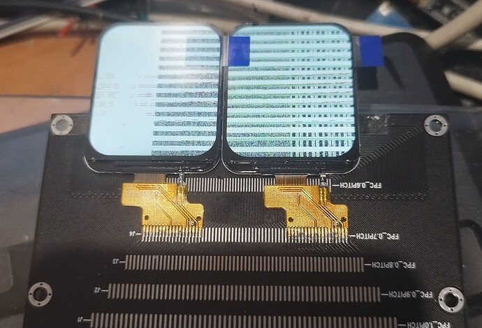
I have modified flush cb function slightly and increased resolution of whole display, like noted in LVGL docs, but I’ve got a shifted lines of picture and garbage. Besides, both of displays are blinking every 0.7-0.8 sec simulatneously.

#define EXAMPLE_LCD_H_RES              480
#define EXAMPLE_LCD_V_RES              280
//...
static void example_lvgl_flush_cb(lv_disp_drv_t *drv, const lv_area_t *area, lv_color_t *color_map)
{
    esp_lcd_panel_handle_t panel_handle = (esp_lcd_panel_handle_t) drv->user_data;
    int offsetx1 = area->x1;
    int offsetx2 = area->x2;
    int offsety1 = area->y1;
    int offsety2 = area->y2;
    // change cs pins to control appropriate display
    gpio_set_level(15,0);
    gpio_set_level(7,1);
                                           //maybe problem is in 'offsetx2/2+1'
    esp_lcd_panel_draw_bitmap(panel_handle, offsetx1, offsety1, offsetx2/2 +1, offsety2 + 1, color_map);
    gpio_set_level(15,1);
    gpio_set_level(7,0);
    
   
    esp_lcd_panel_draw_bitmap(panel_handle, offsetx2/2 + 1, offsety1, offsetx2 + 1, offsety2 + 1, color_map);
 }


I’ll be glad for any real idea. )

You have to split the color_map array according what belongs to left display and right display.

Your code is complete fail. If you expand horizontal need more complicated code with for line by line.
Most simple is expand verticaly. 240x560

I can’t expand vertically. Further I’m going to use narrow displays like 135x240.