I am waiting for the parts to arrive to finish up the build. I made a variable speed 12 volt electric pump controller. I removed the mechanical water pump in my vehicle and replaced it with an electric one. The controller the manufacturer of the pump has offers no adjustability. So I set out to build a replacement. I am waiting for the PCB to arrive and the components to arrive so I can put it all together and test it.
I have the GUI made but I am not liking it all that much. I am using a 3.5" screen and I am trying to put to much information onto the screen which makes it hard to read.
I will post some photos of what the GUI looks like. In a little while.
I know that pain, trying to display 4particle counts + CO2/temp/humdity values plus chart area. I even got desperate enough to ask some AI generators to have a go for me, 1.9" 320x170pixels here (LilyGo T-DisplayS3)
I got my parts in today. I am in the process of assembling the board now. I hit a snag tho and I am not sure if I am going to have to wait to get another part or not. I thought I had pin sockets that had long solder pins on them. It turns out that I don’t and the ones I have are too short to bent into a 90°. I am going to solder the holes closed and lay it flat so I can solder down to the top of the board instead of having the pin go through the board.
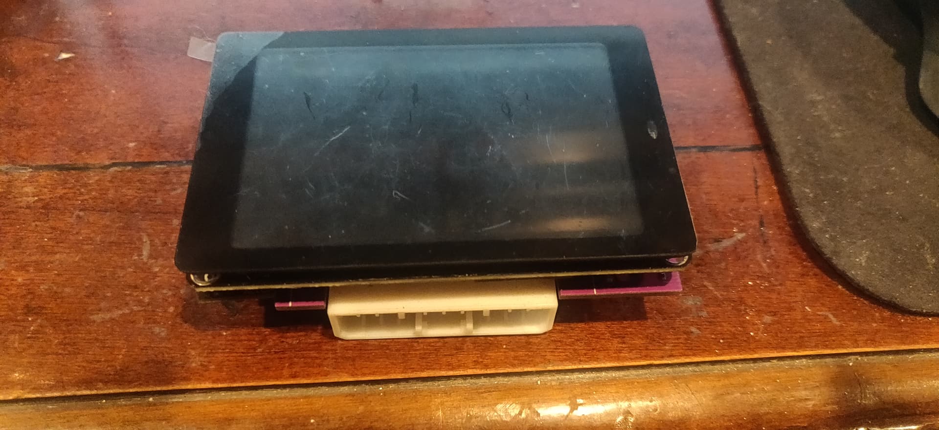
All finished with the board assembly. Gotta wait for my phone to charge up so I can take some photos. I still have to draw up the enclosure and have it 3D printed.
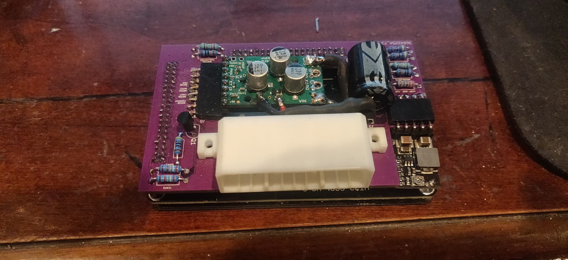
Nice job, looks very sexy in first photo. Then my mind started trying to digest it, is the bottom right (sunken board) a 5v boost? And is the centered header-joined pcb a general power supply board? Also is the main display also got the MCU (esp?) on it? I can only see one transistor, is that all that’s there?
The small board in the corner that is plugged in via a pin header is a 2a 5v buck converter to step down the voltage. This has to go in my vehicle so I needed to have that. The part in the middle that is also plugged in via a header is a 25 amp PWM brushed DC motor driver. The 25 amp rating is what it is able to drive without any heat sinks or fans. It has a maximum rating of 60 amps. I went a bit overboard on it because I wanted to make sure I was not going to have any issues. The maximum the pump is supposed to draw for current is 12 amps. That driver board was the most expensive part of the whole build. I paid something like 40 bucks for it.
The screen has an ESP32-WROVER-B with 4mb flash and 8mb SPIRAM. The display is attached using SPI and every one of the pins is broken out into 2 headers. There is no added “fluff” to this display which is a really nice thing. Every display I have seen you only get 3 or 4 GPIOs to use. All the rest of them are used up on SD card slots and attached to sound drivers or whatever else. As an example. they break out the I2C so you can use i but they have pull down resistors attached to those pins so if you needed to use them to read a low input instead of using them for I2C you wouldn’t be able to do that.
I am sure you have come across the display. It is a WT32-SC01 version 3.3 ESP32 display development board. The cost about 30 bucks so not too bad. There is only a single downfall of it. The pin headers they used are 2.0mm pitch and not the standard 2.54. They went with those to keep things low profile. I do have to say they didn’t have them coming off the side of the display like every other company that makes a display board like this.