Description
I’ve integrated LvGL on my STM32F429-disco successfully and able to achieve high frame rate using both LTDC and DMA2D.
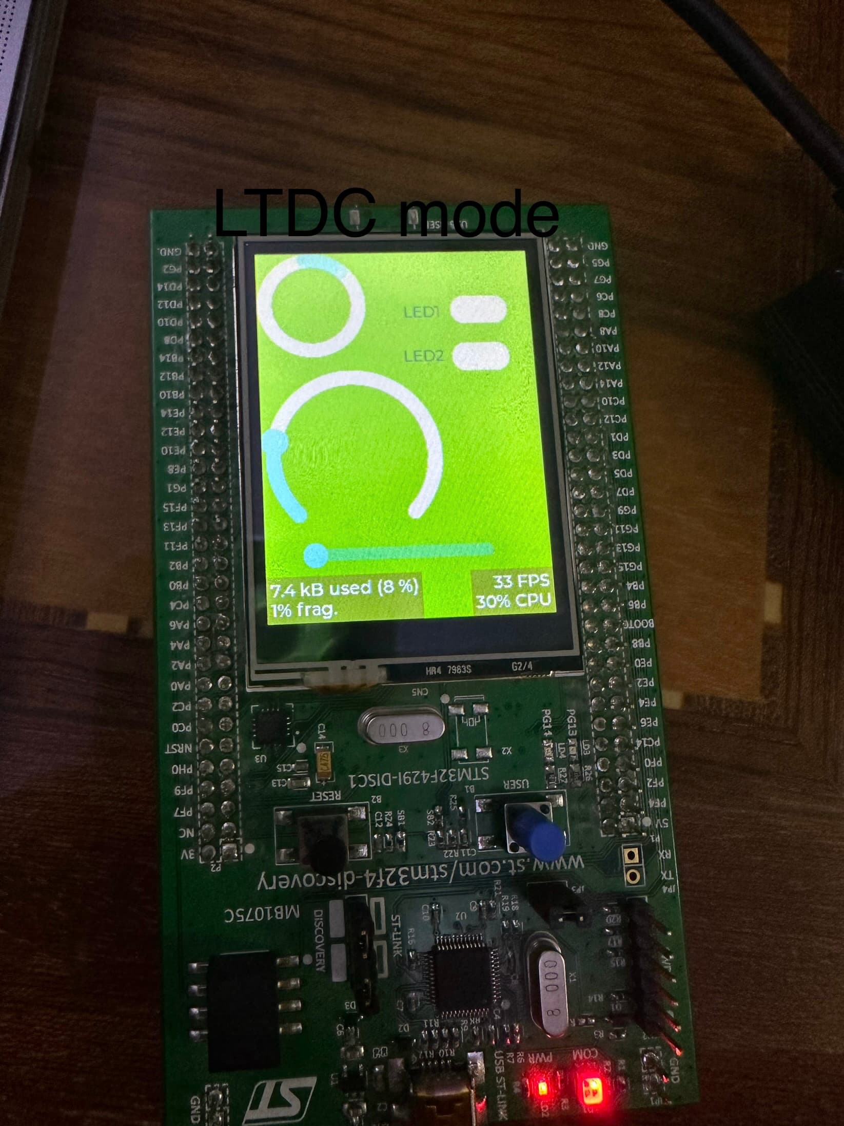
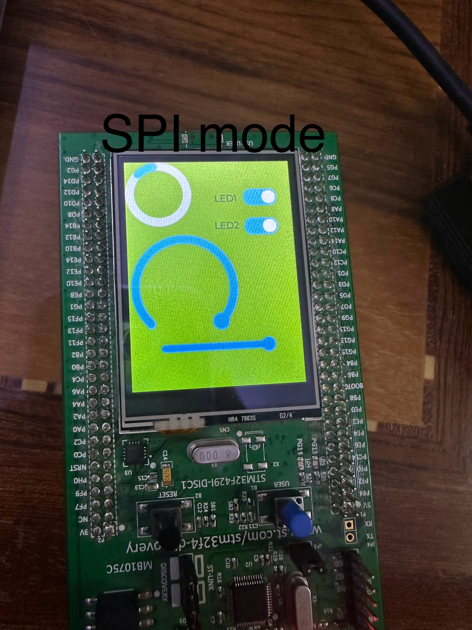
However, out of curiosity, I wanted to use SPI mode of the display and I noticed different in colors rendering.
In SPI mode, the colors are vivid and clear compared to LTDC mode.
I’ve spent like 3 days trying everything related to configuration and LvGL configuration and still same issue.
I’ve attached photos for the issue I am facing.
Touch is working wonderfully.
Any source of the issue?
What MCU/Processor/Board and compiler are you using?
STM32F429-disco
What LVGL version are you using?
V8.3.2
What do you want to achieve?
Same colors as the SPI mode.
What have you tried so far?
LTDC, DMA2D and ILI9341 configuration and same issue.
Screenshot and/or video
You must miss somethink. Normal when same mode for example 16bit is used image is identic. But RGB mode is limited in pinout here to 565 mode. SPI can use too better modes 666 or 24bit 888… Check your init and config functions.
The mode is 16-bit per pixel in both SPI and LTDC.
It should provide same level of colors.
you need to swap the bytes being sent to the display. RGB565 is like this.
r3 r4 r5 r6 r7 g2 g3 g4 g5 g6 g7 b3 b4 b5 b6 b7
You need to change it to
g5 g6 g7 b3 b4 b5 b6 b7 r3 r4 r5 r6 r7 g2 g3 g4
This is done using a simple byte swap.
void byte_swap(uint8_t *buf, uint32_t len) {
    uint16_t *buf_16 = (uint16_t *)buf;
    uint16_t len_16 = len / 2;
    while (len_16--) {
        buf_16[0] = (buf_16[0] << 8) | (buf_16[0] >> 8);
        buf_16++;
    }
}
that will correct your color issue.
if you are using LVGL v8.3x this can also be done by setting the macro LV_COLOR_16_SWAP to a 1. You can add this to your lv_conf.h file.
If using version 9 you can call the function void lv_draw_sw_rgb565_swap(void *buf, uint32_t buf_size_px) from your flush function. This will reorder the bytes for you.
1 Like
The colors are correct when I set them using ltdc.
No need to do swap the colors since this being done on hardware level on ILI9341.
I am wondering why the different in colors?
In SPI, it feels like smartphone while on ltdc, it feels like something from 30 years ago.
I just told you why.
I didn’t design how the interface expects the byte order to be I am just using it. For SPI when using RGB565 you have to change the byte order per pixel.
Try it and see what happens. You will find that the colors get corrected when you do that.
The issue is not the colors, they are correct.
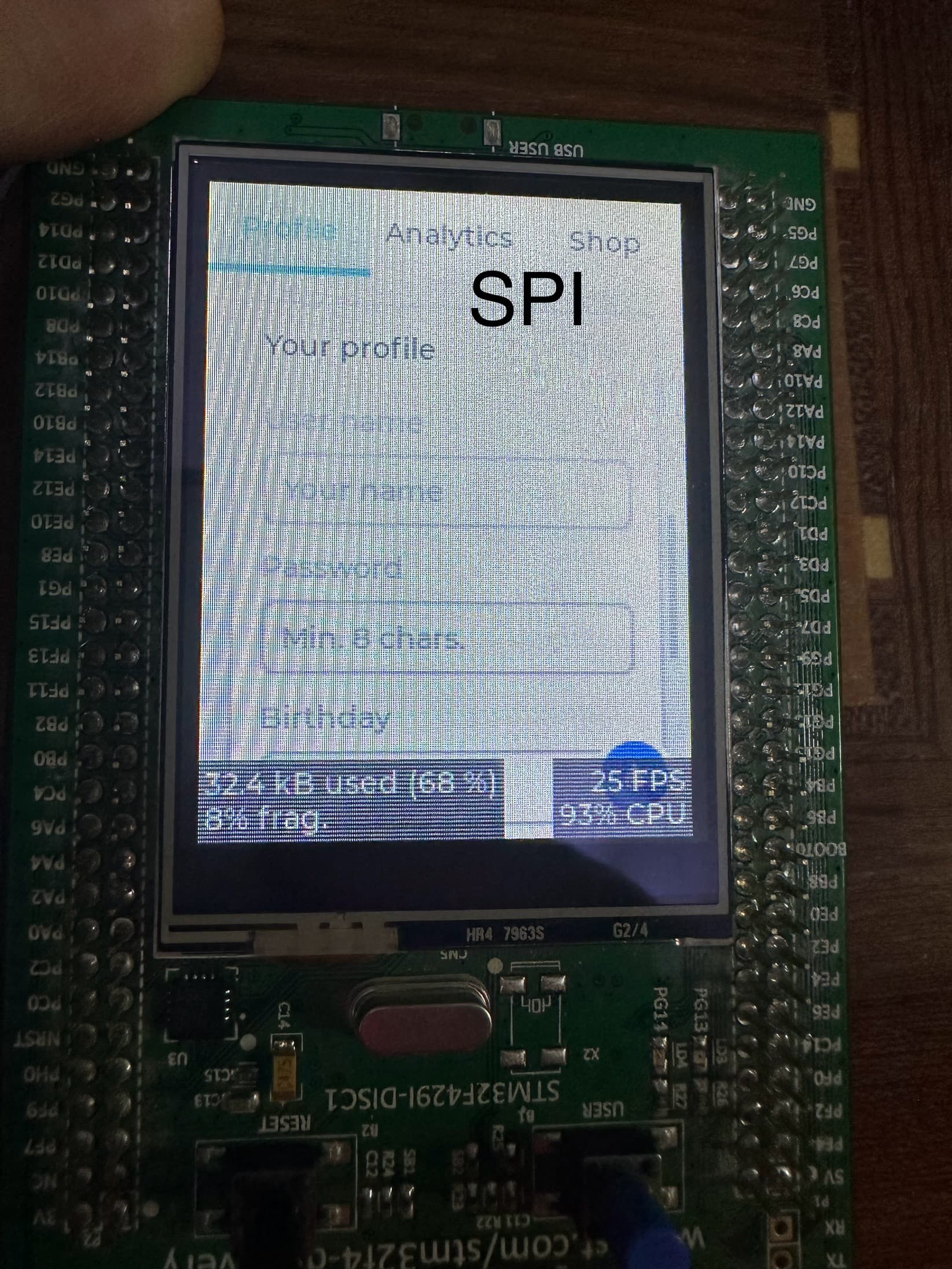
The issue is the contrast. In SPI, I can see all the colors in the widget specially the gray one.
In RGB mode, I can’t see the font at all and the section where to enter your name etc. Thats completely invisible.
I added pictures for the issue of the colors.
As you can see, in SPI, I am able to see the name and password etc.
In LTDC, I am not able to see them at all.
What is the display color depth?
What is the display size (width, height)?
What is your frame buffer size?
Are you using double buffering?
Are you using DMA memory for the frame buffer(s)?
What do you have the render mode set to?
Color depth is set to 16-bit per pixel as I configured the LCD according to the datasheet.
Display size is 320x240 2.4inch.
The lcd frame buffer as following:
attribute((aligned(2))) __IO uint16_t Frame_buffer[FB_SIZE]attribute ((section(“.SDRAM_data”),used));
Yes I am as following:
    attribute((aligned(2)))static lv_color_t buf_1[MY_DISP_HOR_RES*buffer_size]attribute ((section (“.SDRAM_data”)));

    attribute((aligned(2)))static lv_color_t buf_2[MY_DISP_HOR_RES*buffer_size]attribute ((section (“.SDRAM_data”)));
I am using DMA2D to transfer the LvGL buffer to LCD buffer.
I’ve set everything to default in lv_config and only set the color depth and enable examples.
OK so first issue. Your frame buffers are wrong. You need to set them to
display_width * display_height * 2
and you did not answer the rest of my questions.
You should be setting the render mode to direct. In LVGL 8.3x that would be setting the direct_mode field in lv_disp_t to 1.
https://docs.lvgl.io/8.3/porting/display.html?highlight=lv_disp_t#_CPPv4N14_lv_disp_drv_t11direct_modeE
In LVGL V9 that would be passing LV_DISPLAY_RENDER_MODE_DIRECT to the lv_display_set_render_mode function.
https://docs.lvgl.io/master/API/display/lv_display.html#_CPPv426lv_display_set_render_modeP12lv_display_t24lv_display_render_mode_t
1 Like
I’ve set the render mode to 1 which is direct and same thing, no new results.
Regarding multiplying by 2, no need since the buffer is uint16_t. This is if I wanted to use uint8_t rather than uint16_t.
Sorry if my answers were not clear.
The buffer size if 150KB (76800 * 2byte per pixel) which will holds the pixel information.
For the double buffer, I am using two LvGL buffer to render the picture on the scree.
The buffer size is 76800 for each of the buffers.
For the DMA. I am using DMA2D (Chrom-Art Accelerator™ controller) to transfer data from the LvGL buffer to the screen buffer.
1 Like
no you really weren’t clear. Because this.
attribute((aligned(2))) __IO uint16_t Frame_buffer[FB_SIZE]attribute ((section(“.SDRAM_data”),used));
and this
attribute((aligned(2)))static lv_color_t buf_1[MY_DISP_HOR_RES*buffer_size]attribute ((section (“.SDRAM_data”)));
attribute((aligned(2)))static lv_color_t buf_2[MY_DISP_HOR_RES*buffer_size]attribute ((section (“.SDRAM_data”)));
does not tell me what the frame buffer size is. does it? Unless You tell me what buffer_size and FB_SIZE are I have no clue what you are setting the buffer size to.
There is no reason to have the 3rd buffer as it is only going to waste time and resources. When using DMA memory with double buffering the only thing that should be getting passed is the pointer to the buffer. no copying of anything takes place.
From what I have read so far with the board you are using it would appear that the display is using 24 lanes and that means RGB888 color depth and not RGB565. And it also didn’t take me very long to discover that the RGB interface has all kinds of oddities to it that make it extremely difficult to get working.
In order to change an RGB display from RGB888 to RGB565 you either have have specific pins pulled high or low when the display is powered up OR there is a secondary data connection that is usually SPI or I2C to be able to pass parameters and commands to the driver IC to tell it what to do.
Now you said that the data is getting copied from one buffer to the next and if that is the case then both buffers would need to be identical in size. If they are identical in size then why is the same method not being used to set the size for all of the buffers?
If you are using LVGL version 9 the way you are setting up the 2 buffers using lv_color_t is going to give you an incorrect size buffer because lv_color_t always has a size of 3 bytes.
What it looks like is when the screen is being rendered some of the data is being rendered to layer 1 and the rest is being rendered to layer 2 and that is going to cause problems because of how LVGL works. You need to render to 1 layer and only 1 layer. A layer on the STM32 is how it handles the frame buffers. IDK why they call it layer 1 and layer 2 as the terms really do not make any sense.
also from what you said about your buffer sizes that would mean that buffer_size is the display width? That seems rather odd to do.
does not tell me what the frame buffer size is. does it? Unless You tell me what buffer_size and FB_SIZE are I have no clue what you are setting the buffer size to.
Understood, the FB_SIZE is just a macro for 320x240 for the LCD buffer and buffer_size is how many lines to be drawn by the LvGL which is 320. It means the LvGL will update the entire display.
There is no extra buffer, just the LCD buffer which is needed by the LTDC, and two buffers of the LvGL.
From what I have read so far with the board you are using it would appear that the display is using 24 lanes and that means RGB888 color depth and not RGB565. And it also didn’t take me very long to discover that the RGB interface has all kinds of oddities to it that make it extremely difficult to get working.
Actually, STM32F429 doesn’t support RGB888, only RGB565 or RGB666. The onboard LCD, according to the schematic, the TFT is connected to RGB565. Hence, I configured the LTDC accordingly. I even used the initialization sequence from ST board support package and still same issue. I an sending the configuration data using SPI.
A friend of mine tried the same project on his board, same results. This eliminates hardware issue.
What it looks like is when the screen is being rendered some of the data is being rendered to layer 1 and the rest is being rendered to layer 2 and that is going to cause problems because of how LVGL works. You need to render to 1 layer and only 1 layer. A layer on the STM32 is how it handles the frame buffers. IDK why they call it layer 1 and layer 2 as the terms really do not make any sense.
I am using only 1 layer to be rendered. Using two layers will render LvGL useless including DMA2D since it won’t be able to send data for the both layers.
I am not overly versed on the STM32 boards so I am trying to get a better understanding of how this thing is set up. I am not having much luck finding examples of it running using the RGB interface, only SPI. I am not sure why that is. Any references I have found to it running with RGB are saying that they have not been able to get it running using that interface.
I am failing to understand the need for the 3rd buffer. From what my interpretation is of the way it is supposed to work is you create a buffer to be used with each of the 2 layers and those buffers get passed to LVGL. when the flush function gets called you have to tell the stm32 portion that the buffer has been filled and then flip between the 2 layers to the one that has the buffer that was just written to. Tho I am not 100% sure on this.
I recommend search mistake in LTDC config. Read LCD-TFT display controller (LTDC) on STM32 MCUs - Application note chapter 3.3
On SPI pixel data is showed as you send it, but LTDC recalculate pixel from many blending values…
I found a working LvGL example on F429 and when I test it, It is way better.
So, I did a comparison on the register level and they are identical.
Now, I am stumped and have no clue whats going on.
Update:
I was able to narrow it down to faulty initialization sequence of ILI9341.
It was writing to the GRAM rather than directly to the shift register.
Thats was nice to find.
I learnt a lot from this.
That’s fantastic. At least you figured out the issue.