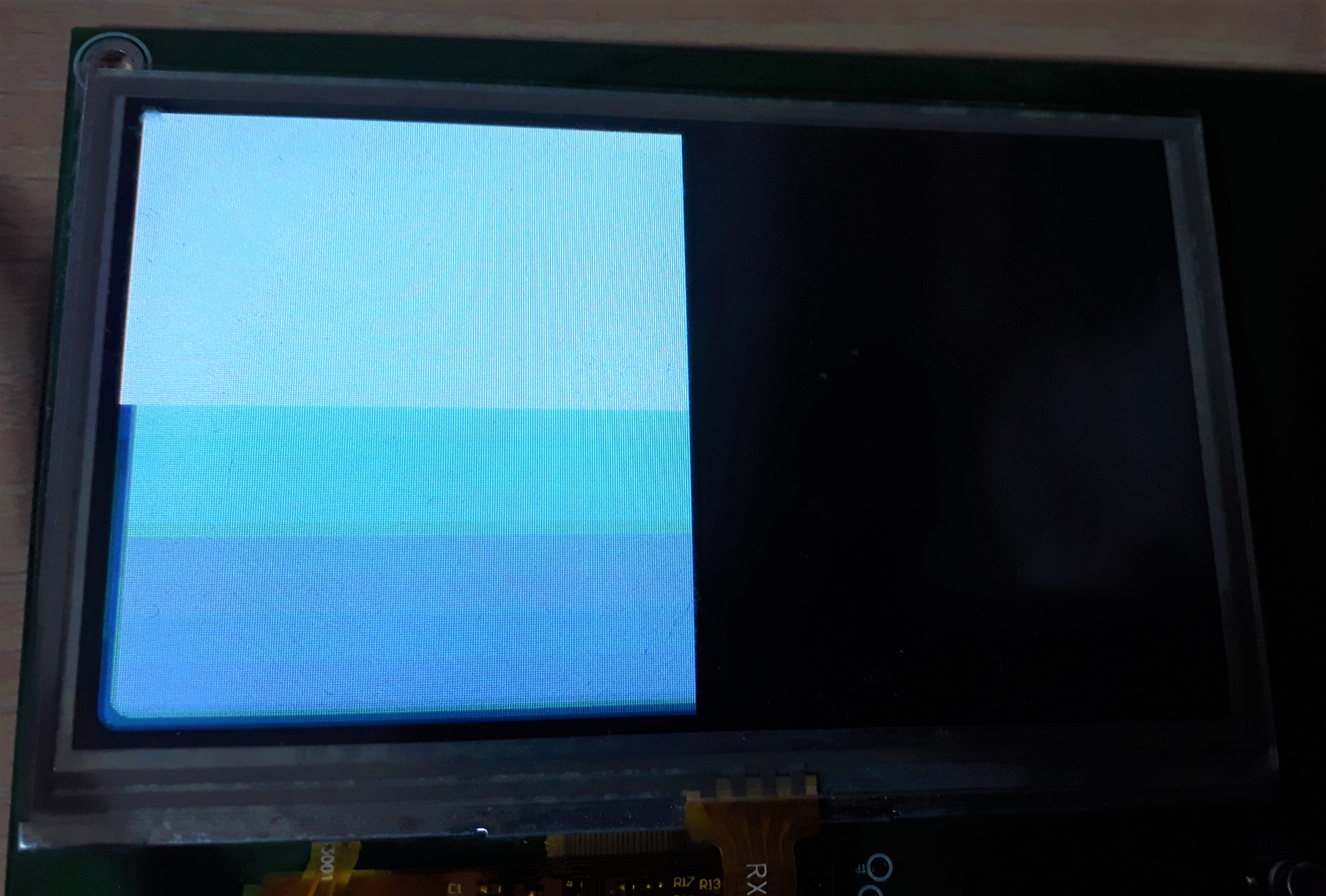
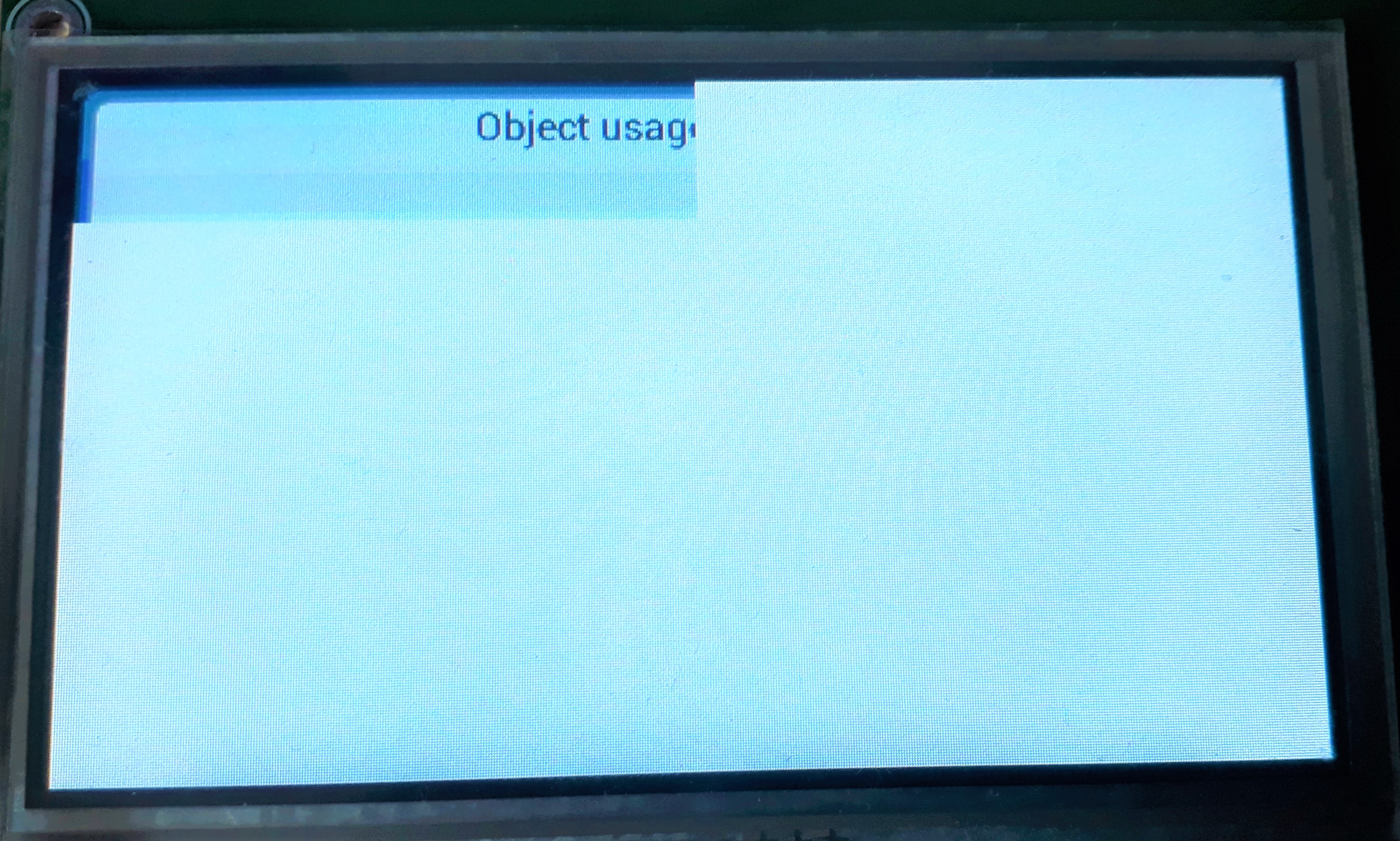
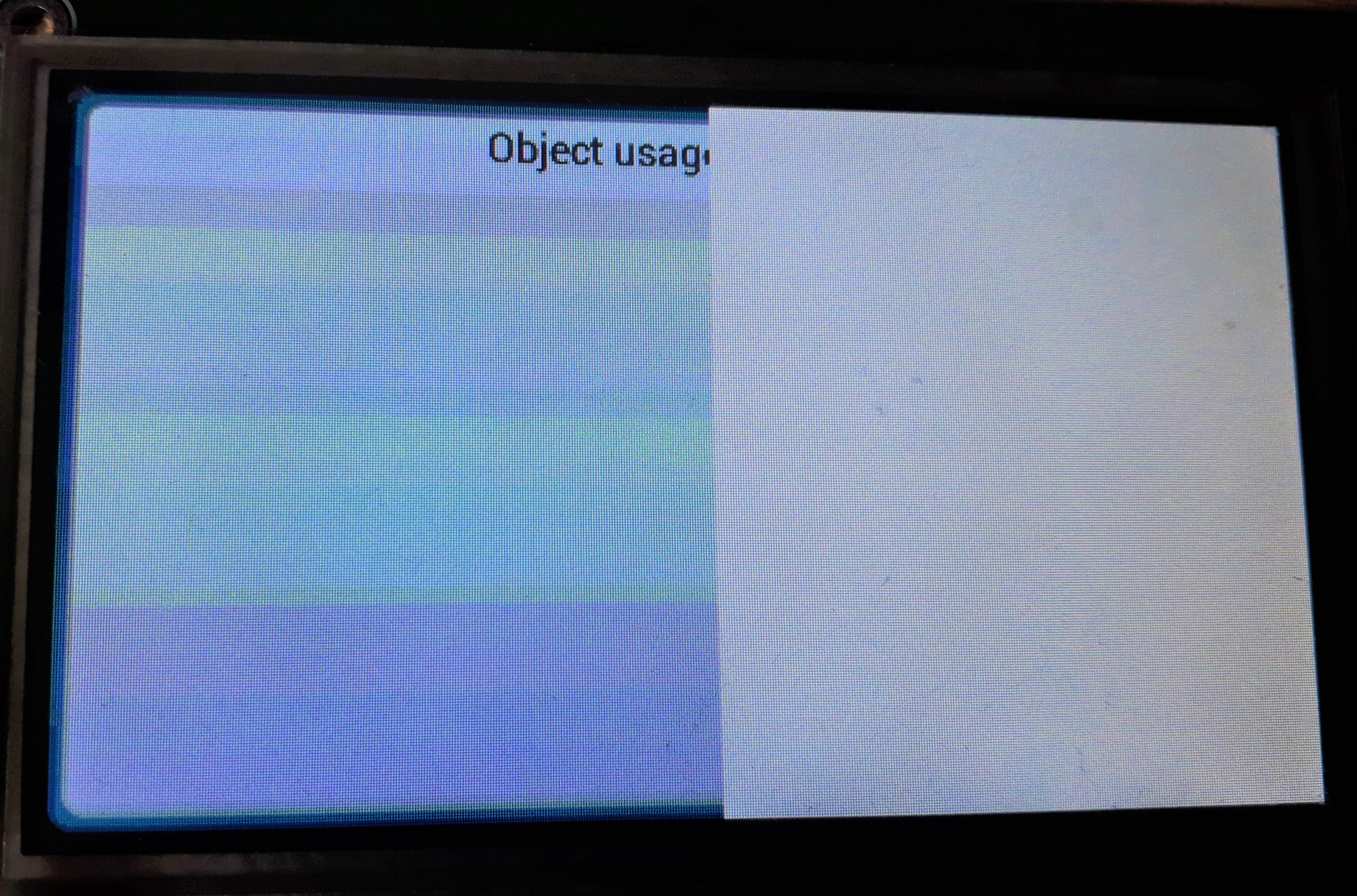
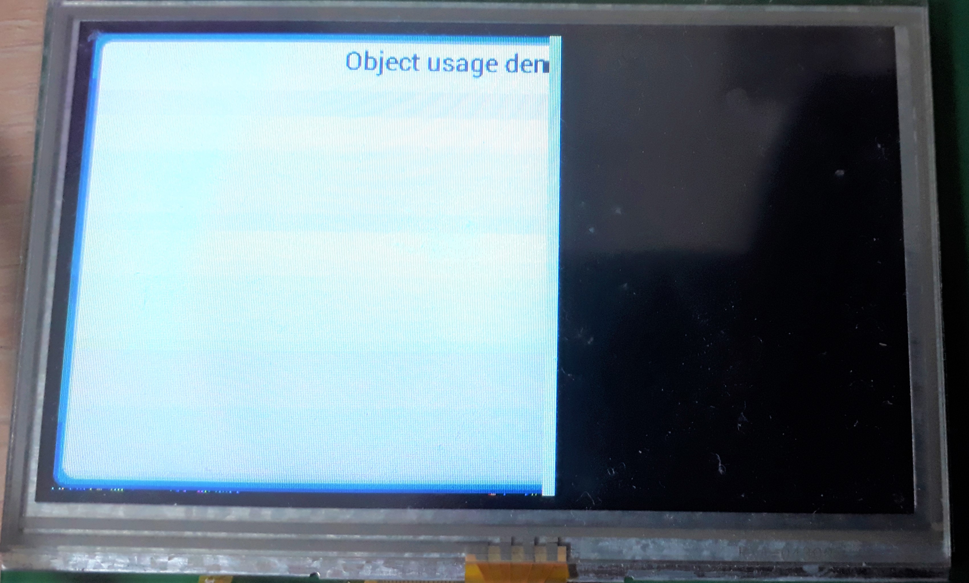
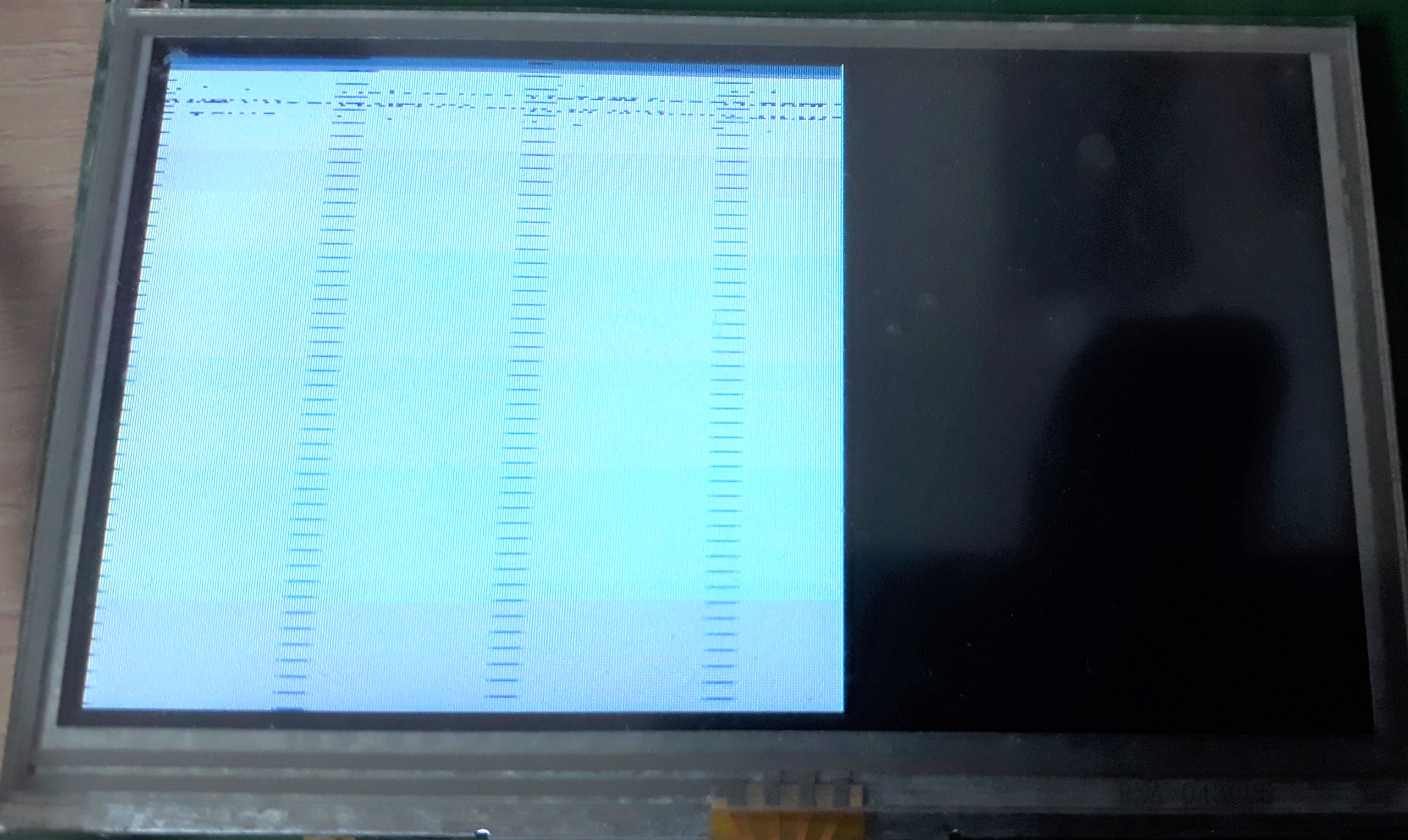
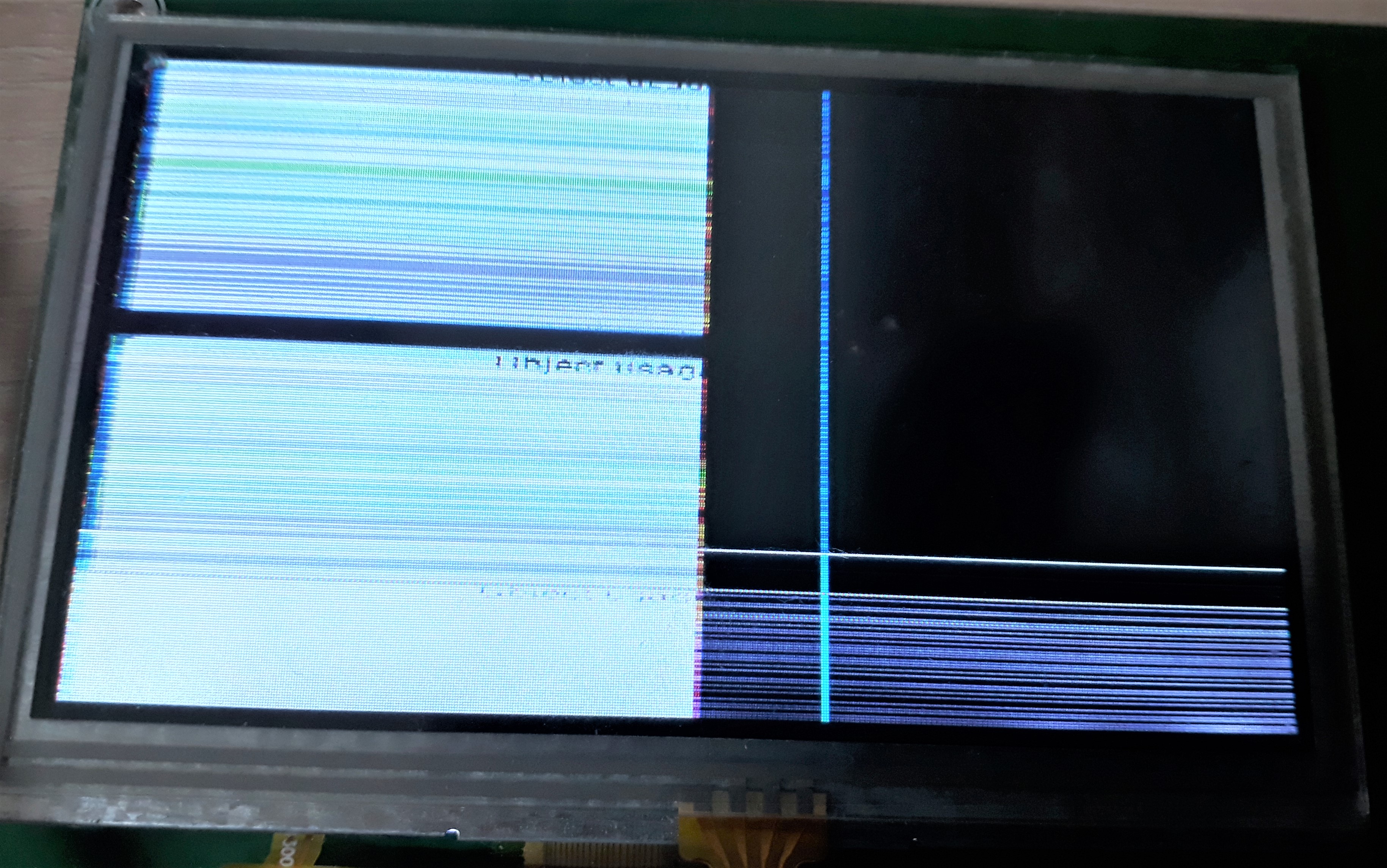
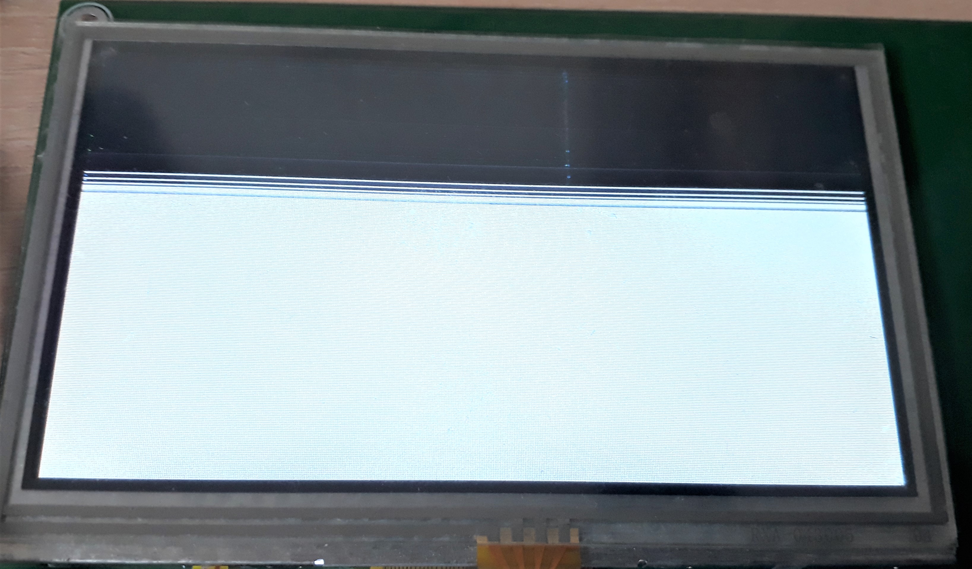
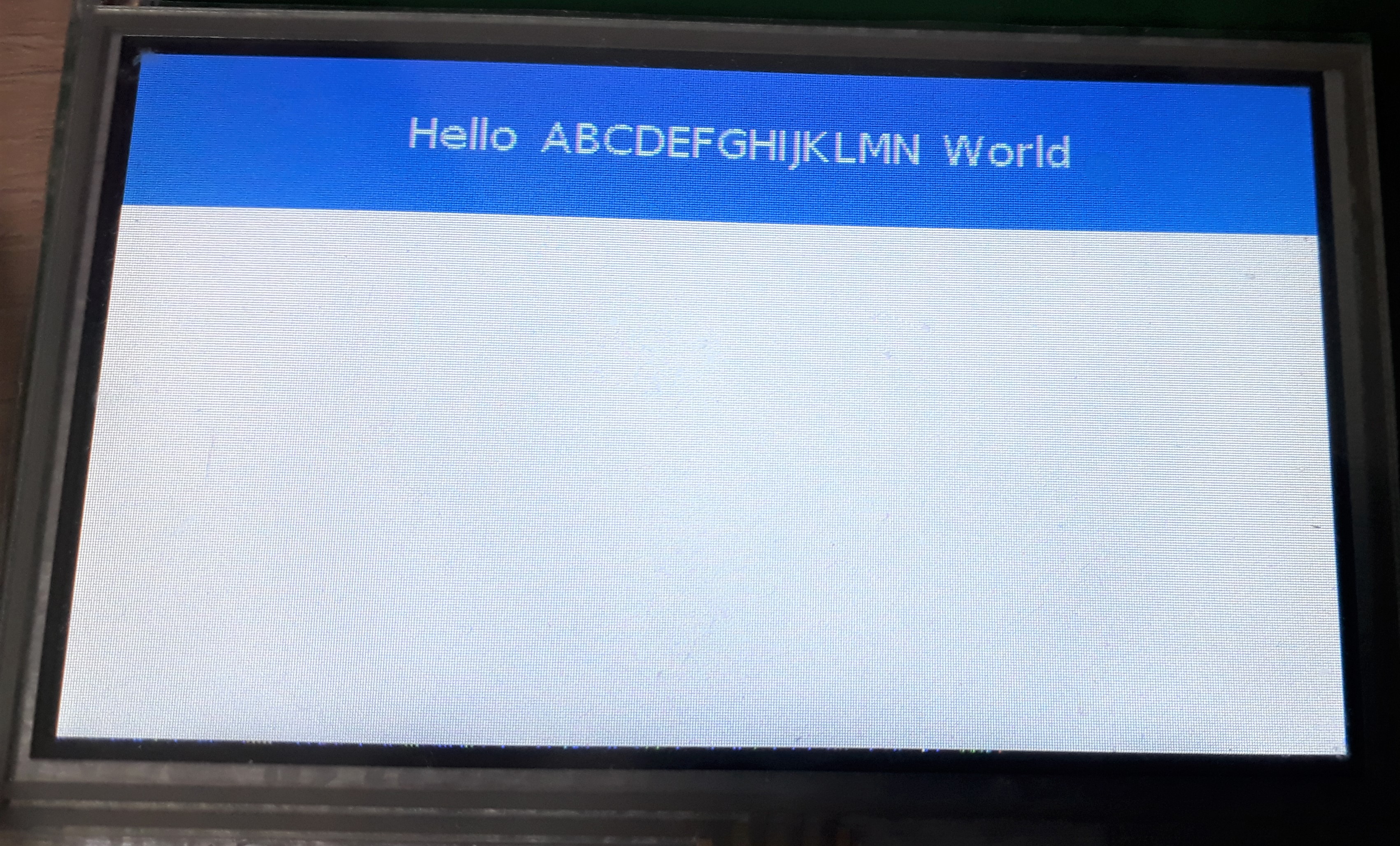
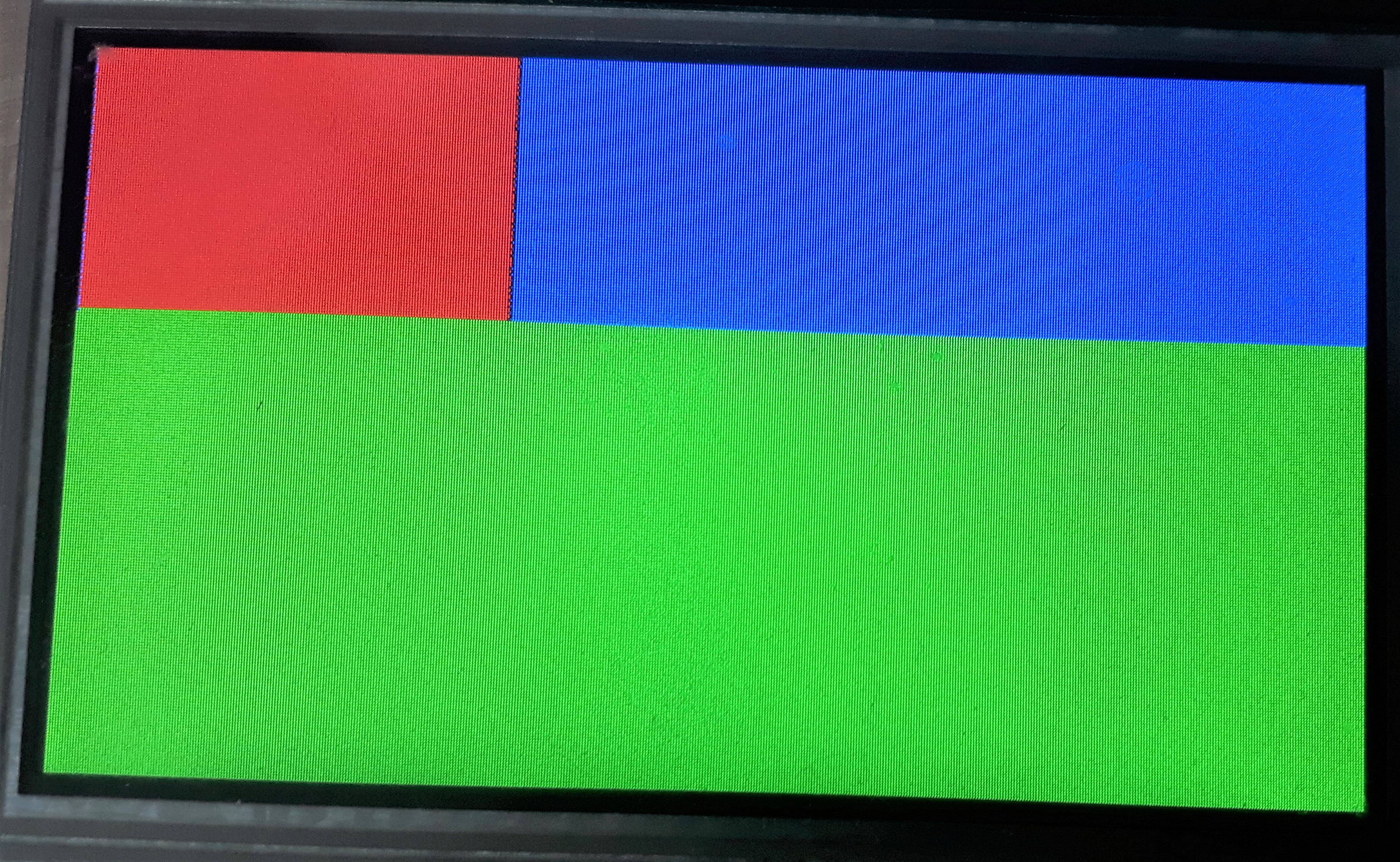
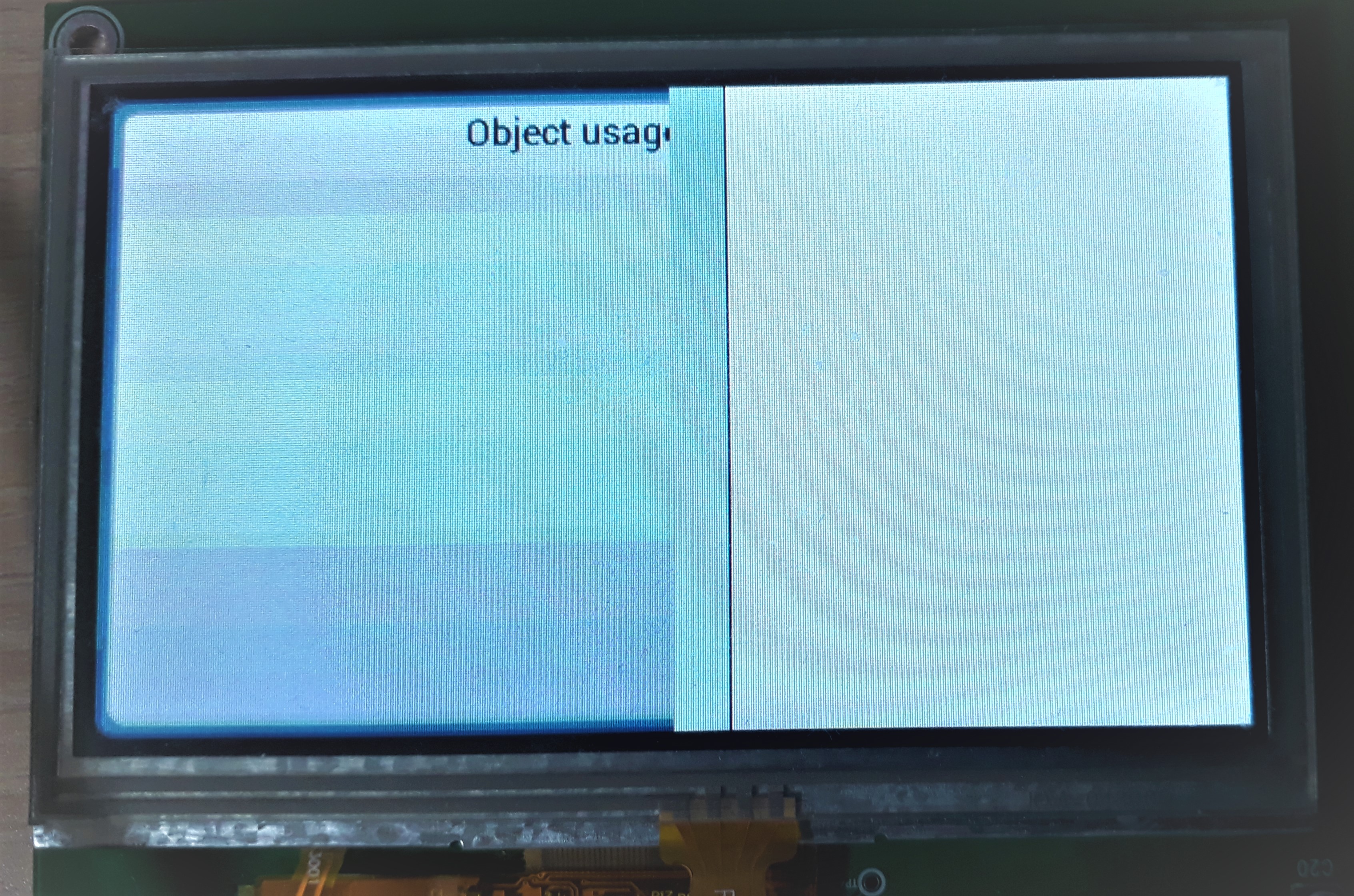
As shown in the screen below, the screen is cut in half and the displayed objects do not seem to be displayed properly.
I’m not sure what the wrong setting is. I’ve been spending two weeks trying to fix it, but I can’t. Please give me a hint to fix it.
Hardware platform is as below:
- MCU: STM32F767
- LCD: LT043A-03AT (480x272)
- LCD controller: OTA5180A
- SDRAM: K4S560832H-UC75 (256Mbit)
- LVGL: 6.0
main.c
int main(void)
{
  SCB_EnableICache();

  HAL_Init();
  SystemClock_Config();
  MX_GPIO_Init();

  lv_init();
  tft_init();

  lv_obj_t * scr = lv_page_create(NULL, NULL);
  lv_disp_load_scr(scr);

  /****************
  * ADD A TITLE
  ****************/
  lv_obj_t * label = lv_label_create(scr, NULL); /*First parameters (scr) is the parent*/
  lv_label_set_text(label, "Object usage demo");  /*Set the text*/
  lv_obj_set_x(label, 150);                        /*Set the x coordinate*/

    while(1) {
        lv_task_handler();
        HAL_Delay(10);
    }
}
tft.c
/**
* @file disp.c
*
*/
/*********************
* INCLUDES
*********************/
#include "lv_conf.h"
#include "lvgl/lvgl.h"
#include <string.h>
#include "tft.h"
#include "stm32f7xx_hal.h"
//#include "ili9341.h"
/*********************
* DEFINES
*********************/
#if TFT_EXT_FB != 0 /* SDRAM: K4S561232H-UC75 */
#define REFRESH_COUNT (823) /* SDRAM refresh counter = (64ms/8K) x 108MHz -20 */
#define SDRAM_BANK_ADDR ((uint32_t)0xC0000000)
#define SDRAM_MEMORY_WIDTH FMC_SDRAM_MEM_BUS_WIDTH_16
#define SDCLOCK_PERIOD FMC_SDRAM_CLOCK_PERIOD_2
#define SDRAM_TIMEOUT ((uint32_t)0xFFFF)
#define SDRAM_MODEREG_BURST_LENGTH_1 ((uint16_t)0x0000)
#define SDRAM_MODEREG_BURST_LENGTH_2 ((uint16_t)0x0001)
#define SDRAM_MODEREG_BURST_LENGTH_4 ((uint16_t)0x0002)
#define SDRAM_MODEREG_BURST_LENGTH_8 ((uint16_t)0x0004)
#define SDRAM_MODEREG_BURST_TYPE_SEQUENTIAL ((uint16_t)0x0000)
#define SDRAM_MODEREG_BURST_TYPE_INTERLEAVED ((uint16_t)0x0008)
#define SDRAM_MODEREG_CAS_LATENCY_2 ((uint16_t)0x0020)
#define SDRAM_MODEREG_CAS_LATENCY_3 ((uint16_t)0x0030)
#define SDRAM_MODEREG_OPERATING_MODE_STANDARD ((uint16_t)0x0000)
#define SDRAM_MODEREG_WRITEBURST_MODE_PROGRAMMED ((uint16_t)0x0000)
#define SDRAM_MODEREG_WRITEBURST_MODE_SINGLE ((uint16_t)0x0200)
#endif
/* DMA Stream parameters definitions. You can modify these parameters to select
a different DMA Stream and/or channel.
But note that only DMA2 Streams are capable of Memory to Memory transfers. */
#define DMA_STREAM DMA2_Stream0
#define DMA_CHANNEL DMA_CHANNEL_0
#define DMA_STREAM_IRQ DMA2_Stream0_IRQn
#define DMA_STREAM_IRQHANDLER DMA2_Stream0_IRQHandler
/**********************
* TYPEDEFS
**********************/
/**********************
* STATIC PROTOTYPES
**********************/
/*These 3 functions are needed by LittlevGL*/
static void tft_flush(lv_disp_drv_t * drv, const lv_area_t * area, lv_color_t * color_p);
#if TFT_USE_GPU != 0
static void gpu_mem_blend(lv_disp_drv_t * drv, lv_color_t * dest, const lv_color_t * src, uint32_t length, lv_opa_t opa);
static void gpu_mem_fill(lv_disp_drv_t * disp_drv, lv_color_t * dest_buf, lv_coord_t dest_width,
const lv_area_t * fill_area, lv_color_t color);
#endif
/*LCD*/
static void LCD_Config(void);
void HAL_LTDC_MspDeInit(LTDC_HandleTypeDef *hltdc);
void HAL_LTDC_MspInit(LTDC_HandleTypeDef *hltdc);
#if TFT_USE_GPU != 0
static void DMA2D_Config(void);
#endif
/*SD RAM*/
#if TFT_EXT_FB != 0
static void SDRAM_Init(void);
static void SDRAM_Initialization_Sequence(SDRAM_HandleTypeDef *hsdram, FMC_SDRAM_CommandTypeDef *Command);
#endif
/*DMA to flush to frame buffer*/
static void DMA_Config(void);
static void DMA_TransferComplete(DMA_HandleTypeDef *han);
static void DMA_TransferError(DMA_HandleTypeDef *han);
static void Error_Handler(void);
/**********************
* STATIC VARIABLES
**********************/
static LTDC_HandleTypeDef LtdcHandle;
#if TFT_USE_GPU != 0
static DMA2D_HandleTypeDef Dma2dHandle;
#endif
#if TFT_EXT_FB != 0
SDRAM_HandleTypeDef hsdram;
FMC_SDRAM_TimingTypeDef SDRAM_Timing;
FMC_SDRAM_CommandTypeDef command;
static __IO uint16_t * my_fb = (__IO uint16_t*) (SDRAM_BANK_ADDR);
#else
static uint16_t my_fb[TFT_HOR_RES * TFT_VER_RES];
#endif
DMA_HandleTypeDef DmaHandle;
static lv_disp_drv_t disp_drv;
static int32_t x1_flush;
static int32_t y1_flush;
static int32_t x2_flush;
static int32_t y2_fill;
static int32_t y_fill_act;
static const lv_color_t * buf_to_flush;
/**********************
* MACROS
**********************/
/**********************
* GLOBAL FUNCTIONS
**********************/
/**
* Initialize your display here
*/
void tft_init(void)
{
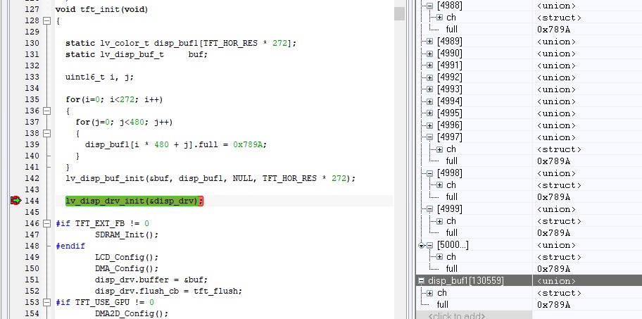
static lv_color_t disp_buf1[TFT_HOR_RES * 272];
static lv_disp_buf_t buf;
lv_disp_buf_init(&buf, disp_buf1, NULL, TFT_HOR_RES * 272);
lv_disp_drv_init(&disp_drv);
#if TFT_EXT_FB != 0
SDRAM_Init();
#endif
LCD_Config();
DMA_Config();
disp_drv.buffer = &buf;
disp_drv.flush_cb = tft_flush;
#if TFT_USE_GPU != 0
DMA2D_Config();
disp_drv.gpu_blend_cb = gpu_mem_blend;
disp_drv.gpu_fill_cb = gpu_mem_fill;
#endif
lv_disp_drv_register(&disp_drv);
}
/**********************
* STATIC FUNCTIONS
**********************/
/**
* Flush a color buffer
* @param x1 left coordinate of the rectangle
* @param x2 right coordinate of the rectangle
* @param y1 top coordinate of the rectangle
* @param y2 bottom coordinate of the rectangle
* @param color_p pointer to an array of colors
*/
static void tft_flush(lv_disp_drv_t * drv, const lv_area_t * area, lv_color_t * color_p)
{
/*Return if the area is out the screen*/
if(area->x2 < 0) return;
if(area->y2 < 0) return;
if(area->x1 > TFT_HOR_RES - 1) return;
if(area->y1 > TFT_VER_RES - 1) return;
/*Truncate the area to the screen*/
int32_t act_x1 = area->x1 < 0 ? 0 : area->x1;
int32_t act_y1 = area->y1 < 0 ? 0 : area->y1;
int32_t act_x2 = area->x2 > TFT_HOR_RES - 1 ? TFT_HOR_RES - 1 : area->x2;
int32_t act_y2 = area->y2 > TFT_VER_RES - 1 ? TFT_VER_RES - 1 : area->y2;
x1_flush = act_x1;
y1_flush = act_y1;
x2_flush = act_x2;
y2_fill = act_y2;
y_fill_act = act_y1;
buf_to_flush = color_p;
/*##-7- Start the DMA transfer using the interrupt mode #*/
/* Configure the source, destination and buffer size DMA fields and Start DMA Stream transfer */
/* Enable All the DMA interrupts */
HAL_StatusTypeDef err;
err = HAL_DMA_Start_IT(&DmaHandle,(uint32_t)buf_to_flush, (uint32_t)&my_fb[y_fill_act * TFT_HOR_RES + x1_flush],
(x2_flush - x1_flush + 1));
if(err != HAL_OK)
{
while(1); /*Halt on error*/
}
}
#if TFT_USE_GPU != 0
/**
* Copy pixels to destination memory using opacity
* @param dest a memory address. Copy 'src' here.
* @param src pointer to pixel map. Copy it to 'dest'.
* @param length number of pixels in 'src'
* @param opa opacity (0, OPA_TRANSP: transparent ... 255, OPA_COVER, fully cover)
*/
static void gpu_mem_blend(lv_disp_drv_t * drv, lv_color_t * dest, const lv_color_t * src, uint32_t length, lv_opa_t opa)
{
/*Wait for the previous operation*/
HAL_DMA2D_PollForTransfer(&Dma2dHandle, 100);
Dma2dHandle.Init.Mode = DMA2D_M2M_BLEND;
/* DMA2D Initialization */
if(HAL_DMA2D_Init(&Dma2dHandle) != HAL_OK)
{
/* Initialization Error */
while(1);
}
Dma2dHandle.LayerCfg[1].InputAlpha = opa;
HAL_DMA2D_ConfigLayer(&Dma2dHandle, 1);
HAL_DMA2D_BlendingStart(&Dma2dHandle, (uint32_t) src, (uint32_t) dest, (uint32_t)dest, length, 1);
}
static void gpu_mem_fill(lv_disp_drv_t * disp_drv, lv_color_t * dest_buf, lv_coord_t dest_width,
const lv_area_t * fill_area, lv_color_t color)
{
/*Wait for the previous operation*/
HAL_DMA2D_PollForTransfer(&Dma2dHandle, 100);
Dma2dHandle.Init.Mode = DMA2D_R2M;
/* DMA2D Initialization */
if(HAL_DMA2D_Init(&Dma2dHandle) != HAL_OK)
{
/* Initialization Error */
while(1);
}
Dma2dHandle.LayerCfg[1].InputAlpha = 0xff;
HAL_DMA2D_ConfigLayer(&Dma2dHandle, 1);
lv_color_t * dest_buf_ofs = dest_buf;
dest_buf_ofs += dest_width * fill_area->y1;
dest_buf_ofs += fill_area->x1;
lv_coord_t area_w = lv_area_get_width(fill_area);
uint32_t i;
for(i = fill_area->y1; i <= fill_area->y2; i++) {
/*Wait for the previous operation*/
HAL_DMA2D_PollForTransfer(&Dma2dHandle, 100);
HAL_DMA2D_BlendingStart(&Dma2dHandle, (uint32_t) lv_color_to32(color), (uint32_t) dest_buf_ofs, (uint32_t)dest_buf_ofs, area_w, 1);
dest_buf_ofs += dest_width;
}
}
#endif
static void LCD_Config(void)
{
LTDC_LayerCfgTypeDef pLayerCfg;
/* Initialization of ILI9341 component*/
//ili9341_Init();
//LT043A_Init();
/* LTDC Initialization -------------------------------------------------------*/
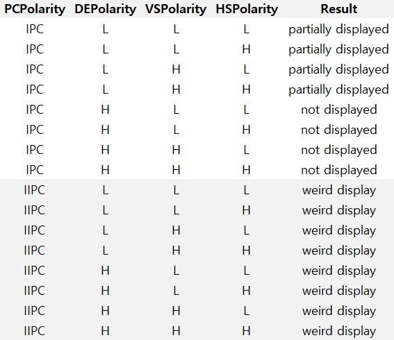
/* Polarity configuration */
/* Initialize the horizontal synchronization polarity as active low */
LtdcHandle.Init.HSPolarity = LTDC_HSPOLARITY_AL;
/* Initialize the vertical synchronization polarity as active low */
LtdcHandle.Init.VSPolarity = LTDC_VSPOLARITY_AL;
/* Initialize the data enable polarity as active low */
LtdcHandle.Init.DEPolarity = LTDC_DEPOLARITY_AL;
/* Initialize the pixel clock polarity as input pixel clock */
LtdcHandle.Init.PCPolarity = LTDC_PCPOLARITY_IPC;
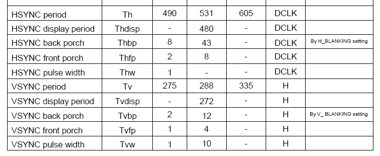
/* Timing configuration (Typical configuration from LT043A-03AT datasheet)
HSYNC pulse width = 1
HSYNC Back Porch = 43
HSYNC Display Peirod = 480
HSYBC Front Porch = 8
VSYNC pulse width = 1
VSYNC Back Porch = 12
VSYNC Display Period = 272
VSYNC Front Porch = 4
*/
/* Timing configuration */
/* Horizontal synchronization width = Hsync - 1*/
LtdcHandle.Init.HorizontalSync = 0;
/* Vertical synchronization height = Vsync - 1 */
LtdcHandle.Init.VerticalSync = 0;
/* Accumulated horizontal back porch = Hsync + HBP - 1 */
LtdcHandle.Init.AccumulatedHBP = 43;
/* Accumulated vertical back porch = Vsync + VBP - 1 */
LtdcHandle.Init.AccumulatedVBP = 12;
/* Accumulated active width = Hsync + HBP + Active Width - 1 */
LtdcHandle.Init.AccumulatedActiveH = 523;
/* Accumulated active height = Vsync + VBP + Active Heigh - 1 */
LtdcHandle.Init.AccumulatedActiveW = 284;
/* Total height = Vsync + VBP + Active Heigh + VFP - 1 */
LtdcHandle.Init.TotalHeigh = 288;
/* Total width = Hsync + HBP + Active Width + HFP - 1 */
LtdcHandle.Init.TotalWidth = 531;
/* Configure R,G,B component values for LCD background color */
LtdcHandle.Init.Backcolor.Blue = 0;
LtdcHandle.Init.Backcolor.Green = 0;
LtdcHandle.Init.Backcolor.Red = 0;
LtdcHandle.Instance = LTDC;
/* Layer1 Configuration ------------------------------------------------------*/
//memset((void*)my_fb, 0x1234, TFT_HOR_RES * TFT_VER_RES);
memset((void*)my_fb, 0xffff, TFT_HOR_RES * TFT_VER_RES);
/* Windowing configuration */
pLayerCfg.WindowX0 = 0;
pLayerCfg.WindowX1 = TFT_HOR_RES;
pLayerCfg.WindowY0 = 0;
pLayerCfg.WindowY1 = TFT_VER_RES;
/* Pixel Format configuration*/
pLayerCfg.PixelFormat = LTDC_PIXEL_FORMAT_RGB565;
/* Start Address configuration : frame buffer is located at FLASH memory */
pLayerCfg.FBStartAdress = (uint32_t)my_fb;
/* Alpha constant (255 totally opaque) */
pLayerCfg.Alpha = 255;
/* Default Color configuration (configure A,R,G,B component values) */
pLayerCfg.Alpha0 = 0;
pLayerCfg.Backcolor.Blue = 0;
pLayerCfg.Backcolor.Green = 0;
pLayerCfg.Backcolor.Red = 0;
/* Configure blending factors */
pLayerCfg.BlendingFactor1 = LTDC_BLENDING_FACTOR1_PAxCA;
pLayerCfg.BlendingFactor2 = LTDC_BLENDING_FACTOR2_PAxCA;
/* Configure the number of lines and number of pixels per line */
pLayerCfg.ImageWidth = TFT_HOR_RES;
pLayerCfg.ImageHeight = TFT_VER_RES;
/* Configure the LTDC */
if(HAL_LTDC_Init(&LtdcHandle) != HAL_OK)
{
/* Initialization Error */
Error_Handler();
}
/* Configure the Background Layer*/
if(HAL_LTDC_ConfigLayer(&LtdcHandle, &pLayerCfg, 0) != HAL_OK)
{
/* Initialization Error */
Error_Handler();
}
}
#if TFT_USE_GPU != 0
/**
* @brief DMA2D Transfer completed callback
* @param hdma2d: DMA2D handle.
* @note This example shows a simple way to report end of DMA2D transfer, and
* you can add your own implementation.
* @retval None
*/
static void DMA2D_TransferComplete(DMA2D_HandleTypeDef *hdma2d)
{
}
/**
* @brief DMA2D error callbacks
* @param hdma2d: DMA2D handle
* @note This example shows a simple way to report DMA2D transfer error, and you can
* add your own implementation.
* @retval None
*/
static void DMA2D_TransferError(DMA2D_HandleTypeDef *hdma2d)
{
}
/**
* @brief DMA2D configuration.
* @note This function Configure the DMA2D peripheral :
* 1) Configure the Transfer mode as memory to memory with blending.
* 2) Configure the output color mode as RGB565 pixel format.
* 3) Configure the foreground
* - first image loaded from FLASH memory
* - constant alpha value (decreased to see the background)
* - color mode as RGB565 pixel format
* 4) Configure the background
* - second image loaded from FLASH memory
* - color mode as RGB565 pixel format
* @retval None
*/
static void DMA2D_Config(void)
{
/* Configure the DMA2D Mode, Color Mode and output offset */
Dma2dHandle.Init.Mode = DMA2D_M2M_BLEND;
Dma2dHandle.Init.ColorMode = DMA2D_RGB565;
Dma2dHandle.Init.OutputOffset = 0x0;
/* DMA2D Callbacks Configuration */
Dma2dHandle.XferCpltCallback = DMA2D_TransferComplete;
Dma2dHandle.XferErrorCallback = DMA2D_TransferError;
/* Foreground Configuration */
Dma2dHandle.LayerCfg[1].AlphaMode = DMA2D_REPLACE_ALPHA;
Dma2dHandle.LayerCfg[1].InputAlpha = 0xFF;
Dma2dHandle.LayerCfg[1].InputColorMode = DMA2D_INPUT_RGB565;
Dma2dHandle.LayerCfg[1].InputOffset = 0x0;
/* Background Configuration */
Dma2dHandle.LayerCfg[0].AlphaMode = DMA2D_REPLACE_ALPHA;
Dma2dHandle.LayerCfg[0].InputAlpha = 0xFF;
Dma2dHandle.LayerCfg[0].InputColorMode = DMA2D_INPUT_RGB565;
Dma2dHandle.LayerCfg[0].InputOffset = 0x0;
Dma2dHandle.Instance = DMA2D;
/* DMA2D Initialization */
if(HAL_DMA2D_Init(&Dma2dHandle) != HAL_OK)
{
/* Initialization Error */
Error_Handler();
}
HAL_DMA2D_ConfigLayer(&Dma2dHandle, 0);
HAL_DMA2D_ConfigLayer(&Dma2dHandle, 1);
}
#endif
/**
* @brief This function handles LTDC global interrupt request.
* @param None
* @retval None
*/
void LTDC_IRQHandler(void)
{
HAL_LTDC_IRQHandler(&LtdcHandle);
}
/**
* @brief LTDC MSP De-Initialization
* This function frees the hardware resources used in this example:
* - Disable the Peripheral's clock
* @param hltdc: LTDC handle pointer
* @retval None
*/
//void HAL_LTDC_MspDeInit(LTDC_HandleTypeDef *hltdc)
//{
/*##-1- Reset peripherals ##################################################*/
/* Enable LTDC reset state */
//__HAL_RCC_LTDC_FORCE_RESET();
/* Release LTDC from reset state */
//__HAL_RCC_LTDC_RELEASE_RESET();
//}
/**
* @brief DMA2D MSP Initialization
* This function configures the hardware resources used in this example:
* - Peripheral's clock enable
* - Peripheral's GPIO Configuration
* @param hdma2d: DMA2D handle pointer
* @retval None
*/
//void HAL_DMA2D_MspInit(DMA2D_HandleTypeDef *hdma2d)
//{
/*##-1- Enable peripherals and GPIO Clocks #################################*/
//__HAL_RCC_DMA2D_CLK_ENABLE();
/*##-2- NVIC configuration ################################################*/
/* NVIC configuration for DMA2D transfer complete interrupt */
//HAL_NVIC_SetPriority(DMA2D_IRQn, 0, 0);
//HAL_NVIC_EnableIRQ(DMA2D_IRQn);
//}
#if TFT_EXT_FB != 0
static void SDRAM_Init(void)
{
/* SDRAM device configuration */
hsdram.Instance = FMC_SDRAM_DEVICE;
/* Timing configuration for 108 MHz of SDRAM clock frequency (216MHz/2 = 108MHz = 9.26ns/clock) */
SDRAM_Timing.LoadToActiveDelay = 2; /* TMRD(TRRD) min=15ns (2x9.26ns) */
SDRAM_Timing.ExitSelfRefreshDelay = 10; /* TXSR: min=? ns (7x9.26ns) */
SDRAM_Timing.SelfRefreshTime = 6; /* TRAS: min=45ns (6x9.26ns) max=120k (ns) */
SDRAM_Timing.RowCycleDelay = 8; /* TRC: min=65ns (8x9.26ns) */
SDRAM_Timing.WriteRecoveryTime = 10; /* TWR: ? Clock cycles */
SDRAM_Timing.RPDelay = 3; /* TRP: min=20ns (3x9.26ns) */
SDRAM_Timing.RCDDelay = 3; /* TRCD: min=20ns (3x9.26ns) */
hsdram.Init.SDBank = FMC_SDRAM_BANK1;
hsdram.Init.ColumnBitsNumber = FMC_SDRAM_COLUMN_BITS_NUM_8;
hsdram.Init.RowBitsNumber = FMC_SDRAM_ROW_BITS_NUM_13;
hsdram.Init.MemoryDataWidth = SDRAM_MEMORY_WIDTH; //16bit
hsdram.Init.InternalBankNumber = FMC_SDRAM_INTERN_BANKS_NUM_4;
hsdram.Init.CASLatency = FMC_SDRAM_CAS_LATENCY_3;
hsdram.Init.WriteProtection = FMC_SDRAM_WRITE_PROTECTION_DISABLE;
hsdram.Init.SDClockPeriod = SDCLOCK_PERIOD; // HCLK/2
hsdram.Init.ReadBurst = FMC_SDRAM_RBURST_ENABLE;
hsdram.Init.ReadPipeDelay = FMC_SDRAM_RPIPE_DELAY_0;
/* Initialize the SDRAM controller */
if(HAL_SDRAM_Init(&hsdram, &SDRAM_Timing) != HAL_OK)
{
/* Initialization Error */
Error_Handler();
}
/* Program the SDRAM external device */
SDRAM_Initialization_Sequence(&hsdram, &command);
}
/**
* @brief Perform the SDRAM external memory initialization sequence
* @param hsdram: SDRAM handle
* @param Command: Pointer to SDRAM command structure
* @retval None
*/
static void SDRAM_Initialization_Sequence(SDRAM_HandleTypeDef *hsdram, FMC_SDRAM_CommandTypeDef *Command)
{
__IO uint32_t tmpmrd =0;
/* Step 3: Configure a clock configuration enable command */
Command->CommandMode = FMC_SDRAM_CMD_CLK_ENABLE;
Command->CommandTarget = FMC_SDRAM_CMD_TARGET_BANK1;
Command->AutoRefreshNumber = 1;
Command->ModeRegisterDefinition = 0;
/* Send the command */
HAL_SDRAM_SendCommand(hsdram, Command, 0x1000);
/* Step 4: Insert 100 ms delay */
HAL_Delay(100);
/* Step 5: Configure a PALL (precharge all) command */
Command->CommandMode = FMC_SDRAM_CMD_PALL;
Command->CommandTarget = FMC_SDRAM_CMD_TARGET_BANK1;
Command->AutoRefreshNumber = 1;
Command->ModeRegisterDefinition = 0;
/* Send the command */
HAL_SDRAM_SendCommand(hsdram, Command, 0x1000);
/* Step 6 : Configure a Auto-Refresh command */
Command->CommandMode = FMC_SDRAM_CMD_AUTOREFRESH_MODE;
Command->CommandTarget = FMC_SDRAM_CMD_TARGET_BANK1;
Command->AutoRefreshNumber = 8;
Command->ModeRegisterDefinition = 0;
/* Send the command */
HAL_SDRAM_SendCommand(hsdram, Command, 0x1000);
/* Step 7: Program the external memory mode register */
tmpmrd = (uint32_t)SDRAM_MODEREG_BURST_LENGTH_1 |
SDRAM_MODEREG_BURST_TYPE_SEQUENTIAL |
SDRAM_MODEREG_CAS_LATENCY_3 |
SDRAM_MODEREG_OPERATING_MODE_STANDARD |
SDRAM_MODEREG_WRITEBURST_MODE_SINGLE;
Command->CommandMode = FMC_SDRAM_CMD_LOAD_MODE;
Command->CommandTarget = FMC_SDRAM_CMD_TARGET_BANK1;
Command->AutoRefreshNumber = 1;
Command->ModeRegisterDefinition = tmpmrd;
/* Send the command */
HAL_SDRAM_SendCommand(hsdram, Command, 0x1000);
/* Step 8: Set the refresh rate counter */
/* (15.62 us x Freq) - 20 */
/* Set the device refresh counter */
HAL_SDRAM_ProgramRefreshRate(hsdram, REFRESH_COUNT);
}
/**
* @brief SDRAM MSP De-Initialization
* This function frees the hardware resources used in this example:
* - Disable the Peripheral's clock
* - Revert GPIO configuration to their default state
* @param hsdram: SDRAM handle pointer
* @retval None
*/
/*
void HAL_SDRAM_MspDeInit(SDRAM_HandleTypeDef *hsdram)
{
*/
/*## Disable peripherals and GPIO Clocks ###################################*/
/*
HAL_GPIO_DeInit(GPIOB, GPIO_PIN_5 | GPIO_PIN_6);
HAL_GPIO_DeInit(GPIOC, GPIO_PIN_0);
HAL_GPIO_DeInit(GPIOD, GPIO_PIN_0 | GPIO_PIN_1 | GPIO_PIN_8 |\
GPIO_PIN_9 | GPIO_PIN_10 | GPIO_PIN_14 |\
GPIO_PIN_15);
HAL_GPIO_DeInit(GPIOE, GPIO_PIN_0 | GPIO_PIN_1 | GPIO_PIN_7 |\
GPIO_PIN_8 | GPIO_PIN_9 | GPIO_PIN_10 |\
GPIO_PIN_11 | GPIO_PIN_12 | GPIO_PIN_13 |\
GPIO_PIN_14 | GPIO_PIN_15);
HAL_GPIO_DeInit(GPIOF, GPIO_PIN_0 | GPIO_PIN_1 | GPIO_PIN_2 |\
GPIO_PIN_3 | GPIO_PIN_4 | GPIO_PIN_5 |\
GPIO_PIN_11 | GPIO_PIN_12 | GPIO_PIN_13 |\
GPIO_PIN_14 | GPIO_PIN_15);
HAL_GPIO_DeInit(GPIOG, GPIO_PIN_0 | GPIO_PIN_1 | GPIO_PIN_4 |\
GPIO_PIN_5 | GPIO_PIN_8 | GPIO_PIN_15);
}
*/
#endif
/**
* @brief Configure the DMA controller according to the Stream parameters
* defined in main.h file
* @note This function is used to :
* -1- Enable DMA2 clock
* -2- Select the DMA functional Parameters
* -3- Select the DMA instance to be used for the transfer
* -4- Select Callbacks functions called after Transfer complete and
Transfer error interrupt detection
* -5- Initialize the DMA stream
* -6- Configure NVIC for DMA transfer complete/error interrupts
* @param None
* @retval None
*/
static void DMA_Config(void)
{
/*## -1- Enable DMA2 clock #################################################*/
__HAL_RCC_DMA2_CLK_ENABLE();
/*##-2- Select the DMA functional Parameters ###############################*/
DmaHandle.Init.Channel = DMA_CHANNEL; /* DMA_CHANNEL_0 */
DmaHandle.Init.Direction = DMA_MEMORY_TO_MEMORY; /* M2M transfer mode */
DmaHandle.Init.PeriphInc = DMA_PINC_ENABLE; /* Peripheral increment mode Enable */
DmaHandle.Init.MemInc = DMA_MINC_ENABLE; /* Memory increment mode Enable */
DmaHandle.Init.PeriphDataAlignment = DMA_PDATAALIGN_HALFWORD; /* Peripheral data alignment : 16bit */
DmaHandle.Init.MemDataAlignment = DMA_PDATAALIGN_HALFWORD; /* memory data alignment : 16bit */
DmaHandle.Init.Mode = DMA_NORMAL; /* Normal DMA mode */
DmaHandle.Init.Priority = DMA_PRIORITY_HIGH; /* priority level : high */
DmaHandle.Init.FIFOMode = DMA_FIFOMODE_ENABLE; /* FIFO mode enabled */
DmaHandle.Init.FIFOThreshold = DMA_FIFO_THRESHOLD_1QUARTERFULL; /* FIFO threshold: 1/4 full */
DmaHandle.Init.MemBurst = DMA_MBURST_SINGLE; /* Memory burst */
DmaHandle.Init.PeriphBurst = DMA_PBURST_SINGLE; /* Peripheral burst */
/*##-3- Select the DMA instance to be used for the transfer : DMA2_Stream0 #*/
DmaHandle.Instance = DMA_STREAM;
/*##-4- Initialize the DMA stream ##########################################*/
if(HAL_DMA_Init(&DmaHandle) != HAL_OK)
{
while(1);
}
/*##-5- Select Callbacks functions called after Transfer complete and Transfer error */
HAL_DMA_RegisterCallback(&DmaHandle, HAL_DMA_XFER_CPLT_CB_ID, DMA_TransferComplete);
HAL_DMA_RegisterCallback(&DmaHandle, HAL_DMA_XFER_ERROR_CB_ID, DMA_TransferError);
/*##-6- Configure NVIC for DMA transfer complete/error interrupts ##########*/
HAL_NVIC_SetPriority(DMA_STREAM_IRQ, 0, 0);
HAL_NVIC_EnableIRQ(DMA_STREAM_IRQ);
}
/**
* @brief DMA conversion complete callback
* @note This function is executed when the transfer complete interrupt
* is generated
* @retval None
*/
static void DMA_TransferComplete(DMA_HandleTypeDef *han)
{
y_fill_act ++;
if(y_fill_act > y2_fill) {
lv_disp_flush_ready(&disp_drv);
} else {
buf_to_flush += x2_flush - x1_flush + 1;
/*##-7- Start the DMA transfer using the interrupt mode ####################*/
/* Configure the source, destination and buffer size DMA fields and Start DMA Stream transfer */
/* Enable All the DMA interrupts */
if(HAL_DMA_Start_IT(han,(uint32_t)buf_to_flush, (uint32_t)&my_fb[y_fill_act * TFT_HOR_RES + x1_flush],
(x2_flush - x1_flush + 1)) != HAL_OK)
{
while(1); /*Halt on error*/
}
}
}
/**
* @brief DMA conversion error callback
* @note This function is executed when the transfer error interrupt
* is generated during DMA transfer
* @retval None
*/
static void DMA_TransferError(DMA_HandleTypeDef *han)
{
}
/**
* @brief This function handles DMA Stream interrupt request.
* @param None
* @retval None
*/
void DMA_STREAM_IRQHANDLER(void)
{
/* Check the interrupt and clear flag */
HAL_DMA_IRQHandler(&DmaHandle);
}
/**
* @brief This function is executed in case of error occurrence.
* @param None
* @retval None
*/
static void Error_Handler(void)
{
while(1)
{
}
}