Stacking the meter into the dial (I need three hands of different lengths and two scales) seems a bit cumbersome, so it’s particularly desirable that LVGL will consider adding a dial widget in the near future
Could you send an image to better understand what you imagined?
Looks like the translator is not very accurate  , I mean, I need to draw a watch dial for smart watches, similar to figure 1, but there is no corresponding widget can achieve directly, so I refer to guage.c and modify, effect is probably as shown in figure 2, if there is a watch dial widget (like guage widget) can call a function directly, will be very convenient. In summary, it is hoped that the future effect of Figure 1 can be achieved with a widget.(This paragraph is still a translation. I don’t know if it is clearly described. Thank you very much for your patience.)
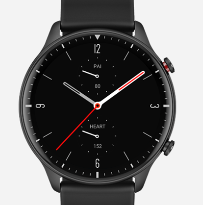
Figure 1
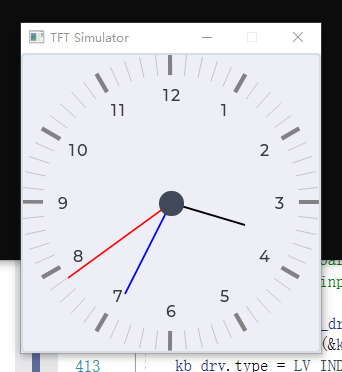
Figure 2
I see thank you.
Noted!
how did you set the needle to different lenth,i have try to use img to set the needle,but only could be seted the same pictrue
I copied guage.c and modified it, such as the lv_gauge_draw_needle() function, then added it as a widget of my own, similar modifications can also make different Pointers to different images. The modification looks something like this:
static void lv_dial_draw_needle(lv_obj_t* dial, const lv_area_t* clip_area)
{
lv_dial_ext_t* ext = lv_obj_get_ext_attr(dial);
lv_style_int_t pad = lv_obj_get_style_pad_inner(dial, LV_DIAL_PART_NEEDLE);
lv_style_int_t left = lv_obj_get_style_pad_left(dial, LV_DIAL_PART_MAIN);
lv_style_int_t right = lv_obj_get_style_pad_right(dial, LV_DIAL_PART_MAIN);
lv_style_int_t top = lv_obj_get_style_pad_top(dial, LV_DIAL_PART_MAIN);

lv_coord_t r = (lv_obj_get_width(dial) - left - right) / 2 - pad;
lv_coord_t r_needle[3];     //三根指针长度不一,各自分开储存   //----- 增加 - By XXX 20201116
for (uint8_t needle_id = 0; needle_id < 3; needle_id++) //将 needle_pad[3] 代入计算   //----- 增加 - By XXX 20201116
{
    r_needle[needle_id] = (lv_obj_get_width(dial) - left - right) / 2 - needle_pad[needle_id];
}
lv_coord_t x_ofs = dial->coords.x1 + r + left + pad;
lv_coord_t y_ofs = dial->coords.y1 + r + top + pad;
uint16_t angle = lv_linemeter_get_scale_angle(dial);
int16_t angle_ofs = 90 + (360 - angle) / 2 + lv_dial_get_angle_offset(dial);
int16_t min = lv_dial_get_min_value(dial);
int16_t max = lv_dial_get_max_value(dial);
lv_point_t p_mid;
lv_point_t p_end;
uint8_t i;

lv_draw_line_dsc_t line_dsc;
lv_draw_img_dsc_t img_dsc;
if (ext->needle_img == NULL) {
    lv_draw_line_dsc_init(&line_dsc);
    lv_obj_init_draw_line_dsc(dial, LV_DIAL_PART_NEEDLE, &line_dsc);
}
else {
    lv_draw_img_dsc_init(&img_dsc);
    lv_obj_init_draw_img_dsc(dial, LV_DIAL_PART_NEEDLE, &img_dsc);
}

p_mid.x = x_ofs;
p_mid.y = y_ofs;
for (i = 0; i < ext->needle_count; i++) {
    /*Calculate the end point of a needle*/
    int16_t needle_angle =
        (ext->values[i] - min) * angle / (max - min) + angle_ofs;

    /*Draw line*/
    if (ext->needle_img == NULL) {
        //p_end.y = (_lv_trigo_sin(needle_angle) * r) / LV_TRIGO_SIN_MAX + y_ofs;
        //p_end.x = (_lv_trigo_sin(needle_angle + 90) * r) / LV_TRIGO_SIN_MAX + x_ofs;
        p_end.y = (_lv_trigo_sin(needle_angle) * r_needle[i]) / LV_TRIGO_SIN_MAX + y_ofs;   //----- 修改 - By XXX 20201116
        p_end.x = (_lv_trigo_sin(needle_angle + 90) * r_needle[i]) / LV_TRIGO_SIN_MAX + x_ofs;   //----- 修改 - By XXX 20201116

        /*Draw the needle with the corresponding color*/
        if (ext->needle_colors != NULL) line_dsc.color = ext->needle_colors[i];

        line_dsc.width = needle_width[i];   //三根指针不同宽度  //----- 增加 - By XXX 20201116
        lv_draw_line(&p_mid, &p_end, clip_area, &line_dsc);
    }
    /*Draw image*/
    else {
        lv_img_header_t info;
        //lv_img_decoder_get_info(ext->needle_img, &info);
        lv_img_decoder_get_info(needle_img[i], &info);    //三根指针不同图片  //----- 修改 - By XXX 20201126

        lv_area_t a;
        //a.x1 = dial->coords.x1 + lv_area_get_width(&dial->coords) / 2 - ext->needle_img_pivot.x;
        //a.y1 = dial->coords.y1 + lv_area_get_height(&dial->coords) / 2 - ext->needle_img_pivot.y;
        a.x1 = dial->coords.x1 + lv_area_get_width(&dial->coords) / 2 - needle_img_pivot[i].x;    //----- 修改 - By XXX  20201126
        a.y1 = dial->coords.y1 + lv_area_get_height(&dial->coords) / 2 - needle_img_pivot[i].y;   //----- 修改 - By XXX  20201126
        a.x2 = a.x1 + info.w - 1;
        a.y2 = a.y1 + info.h - 1;
        //img_dsc.pivot.x = ext->needle_img_pivot.x;
        //img_dsc.pivot.y = ext->needle_img_pivot.y;
        img_dsc.pivot.x = needle_img_pivot[i].x;  //----- 修改 - By XXX 20201126
        img_dsc.pivot.y = needle_img_pivot[i].y;  //----- 修改 - By XXX 20201126

        if (ext->needle_colors != NULL) img_dsc.recolor = ext->needle_colors[i];

        needle_angle = (needle_angle * 10);
        if (needle_angle > 3600) needle_angle -= 3600;
        img_dsc.angle = needle_angle;
        //lv_draw_img(&a, clip_area, ext->needle_img, &img_dsc);
        lv_draw_img(&a, clip_area, needle_img[i], &img_dsc);  //----- 修改 - By XXX 20201126
    }
}

lv_draw_rect_dsc_t mid_dsc;
lv_draw_rect_dsc_init(&mid_dsc);
lv_obj_init_draw_rect_dsc(dial, LV_DIAL_PART_NEEDLE, &mid_dsc);
lv_style_int_t size = lv_obj_get_style_size(dial, LV_DIAL_PART_NEEDLE) / 2;
lv_area_t nm_cord;
nm_cord.x1 = x_ofs - size;
nm_cord.y1 = y_ofs - size;
nm_cord.x2 = x_ofs + size;
nm_cord.y2 = y_ofs + size;
lv_draw_rect(&nm_cord, clip_area, &mid_dsc);
}
Thanks. A few days ago I used the rotation function of IMG to implement analog Clock instead of using the gauge widget because it all looked the same when I set the needle img_src