So I have been able to move a little farther along !!!
see…
So I have been able to move a little farther along !!!
see…
Allmost there…
since you are using the CS line it should only be a matter of flipping the states on the CS pins for the different devices. You can delete the lv timer object that is stored in lv_indev_t and recreate it when you are done doing whatever needs to be done with the SD card. It really shouldn’t be all that difficult to do.
So what I ended up doing is using…
disp.event_loop.disable()
disp.event_loop.enable()
These comands apear to stop and start lvgl.
def sd_write(file,info,w):
    disp.event_loop.disable()
    time.sleep(.05)
    try:
        with open(file, w) as f:
            f.write(info)
    except Exception as e:
            print(e)
    disp.event_loop.enable()
This discussion is too advanced for me.
Does anyone know an intermediate solution?
So I can use TouchScreen and SDCard?
I put details of my problem in this post: https://forum.lvgl.io/t/sd-card-disable-my-touch-screen-help-me/14130v
I believe there is also a function you can use to disable the indev driver when you are going to use the SD card and then enable it again once you are done.
What would this function be?
I don’t know if it exists in version 8 or if it is new in version 9. I believe the function is lv_indev_enable.
I still don’t understand how to do this.
It would be like this: When I use the SD card, would I disable it? Would it be this ?
yes you disable the touch driver in LVGL using that function use the SD card and then enable the touch driver using the same function once you finished using the SD card.
These are my functions that start LVGL.
Could you help me how can I disable and enable this feature?
Sorry for the layman’s question, I’m a little lost.
I even made a post but no one has responded yet.
void setupDisplay(){
        lcd.begin();
        lcd.setRotation(0);
        lcd.fillScreen(TFT_BLACK);
        lcd.setTouch(calData);
        delay(100);

        lv_init();

        lv_disp_draw_buf_init( &draw_buf, buf1, NULL, screenWidth * screenHeight / 13 );

        static lv_disp_drv_t disp_drv;
        lv_disp_drv_init( &disp_drv );
        //Display driver port of LVGL
        disp_drv.hor_res = screenWidth;
        disp_drv.ver_res = screenHeight;
        disp_drv.flush_cb = my_disp_flush;
        disp_drv.draw_buf = &draw_buf;
        lv_disp_drv_register( &disp_drv );

        static lv_indev_drv_t indev_drv;
        lv_indev_drv_init( &indev_drv );
        indev_drv.type = LV_INDEV_TYPE_POINTER;
        indev_drv.read_cb = my_touchpad_read;
        lv_indev_drv_register( &indev_drv );

        //f_progressoDisplay("Iniciando Sistema...", 500);

}
I don’t see any function or code that is for reading from the SD card. need to have that in place for me to be able to show you where to place those function calls.
Below is the setup code, which initializes the SD Card:
void setupSDCard(){
        if(!SD.begin()){
            Serial.println("Card Mount Failed");
            return;
        }

        uint8_t cardType = SD.cardType();

        if(cardType == CARD_NONE){
            Serial.println("No SD card attached");
            return;
        }

        Serial.print("SD Card Type: ");
        if(cardType == CARD_MMC){
            Serial.println("MMC");
            strcpy(SD_.Tipo, "MMC");
        } else if(cardType == CARD_SD){
            Serial.println("SDSC");
            strcpy(SD_.Tipo, "SDSC");
        } else if(cardType == CARD_SDHC){
            Serial.println("SDHC");
            strcpy(SD_.Tipo, "SDHC");
        } else {
            Serial.println("UNKNOWN");
            strcpy(SD_.Tipo, "NOT");
        }

        uint64_t cardSize = SD.cardSize() / (1024 * 1024);
        SD_.Tam = cardSize;
        SD_.TotalSpace = SD.totalBytes() / (1024 * 1024);
        SD_.Uso = SD.usedBytes() / (1024 * 1024);
        //----------------------------------------------------
        Serial.printf("SD Card Size: %lluMB\n", cardSize);
        Serial.printf("Total space: %lluMB\n", SD_.TotalSpace);
        Serial.printf("Used space: %lluMB\n", SD_.Uso);

}
Below is the function I call to use the card:
void v_Datalogger(void *parameters){
      Serial.println("Ponto A");
      TickType_t now;now = xTaskGetTickCount();

      while(1){
              Serial.println("Ponto B");
              Serial.println(data_formatadaX);
              Serial.println(datahora_formatadaX);

              DataLogger_.NomeArq = f_CriaArq();
              //DataLogger_.NomeArq = "/mapa.csv";
              Serial.println("Ponto C");
              //time_t tt = time(NULL);//Obtem o tempo atual em segundos. Utilize isso sempre que precisar obter o tempo atual
              //data = *gmtime(&tt);//Converte o tempo atual e atribui na estrutura
              //strftime(data_formatadaX, 64, "%d/%m/%Y %H:%M:%S", &data);//Cria uma String formatada da estrutura "data"
              //------------------------------------------------------------------------------------------------------------------------
              if (xSemaphoreTake(xMutexArq, 200)) {
                  Serial.println("Ponto D");
                  File oFile = SPIFFS.open(DataLogger_.NomeArq, FILE_APPEND);if (!oFile){Serial.println("Failed to open config file for writing");}
                  char buffer[128];
                  snprintf(buffer, sizeof(buffer), "%s;%.2f", datahora_formatadaX, tempC);
                  oFile.println(buffer);
                  oFile.close();
                  xSemaphoreGive(xMutexArq);
              }
              //-----------------------------------------------------------------------------------------------------------------------
              vTaskDelayUntil(&now,pdMS_TO_TICKS(DataLogger_.Intervalo));
      }
}
char * f_CriaArq() {
    Serial.println("Ponto B.2");
    static char NomeArq[64];
    snprintf(NomeArq, sizeof(NomeArq), "/%s.csv", data_formatadaX);
    char *nomeArquivo = (char *)malloc(strlen(NomeArq) + 1);
    strcpy(nomeArquivo, NomeArq);
    Serial.println("Ponto B.3");
    return nomeArquivo;
}
In addition, of course, to the function that initializes LVGL with the touchScreen:
void setupDisplay(){
        lcd.begin();
        lcd.setRotation(0);
        lcd.fillScreen(TFT_BLACK);
        lcd.setTouch(calData);
        delay(100);

        lv_init();

        lv_disp_draw_buf_init( &draw_buf, buf1, NULL, screenWidth * screenHeight / 13 );

        static lv_disp_drv_t disp_drv;
        lv_disp_drv_init( &disp_drv );
        //Display driver port of LVGL
        disp_drv.hor_res = screenWidth;
        disp_drv.ver_res = screenHeight;
        disp_drv.flush_cb = my_disp_flush;
        disp_drv.draw_buf = &draw_buf;
        lv_disp_drv_register( &disp_drv );

        static lv_indev_drv_t indev_drv;
        lv_indev_drv_init( &indev_drv );
        indev_drv.type = LV_INDEV_TYPE_POINTER;
        indev_drv.read_cb = my_touchpad_read;
        lv_indev_drv_register( &indev_drv );

        //f_progressoDisplay("Iniciando Sistema...", 500);

}
But the problem occurs exactly when I do SD.Begin(), from that moment on the screen’s touchscreen stops working.
And there’s no point giving SD.End(), it won’t work again.
There is some issue that has to do with Software SPI and Hardware SPI, but I don’t know how to resolve it.
ok so what it appears you are using is some external library for handling the LCD screen. I have not seen any code for the touchscreen so I am guessing that the touchscreen is also handled by an external library. The SD card code seems to be running in a thread of some kind because you are checking some kind of a sephamore.
the SDCard reader and the touch panel use SPI to communicate with the MCU. MCU’s can have multiple SPIBus implementations on them so there is what is called a host id to be able to identify them. In order to have more than a single device on an SPI bus 2 things must be done. The first thing is that all devices on the bust may have different software drivers. In your use case you have a software driver for the touch and another one for the SD Card. Each of those 2 drivers need to be told to utilize the exact same bus. how this is done is by passing the same pins but also making sure that the same host number gets passed as well. The second thing is that each of the devices also MUST have their own CS connection to the MCU. This is not something that can be shared. The CS line is what tells a device if it is able to receive or transmit on the bus.
From looking at your code I believe that you have an issue with the software driver that you are using. LVGL’s driver for the touch is simply a way to get the data from the touch driver into LVGL, nothing more. If you are having an issue with being able to use the SDCard with the touch screen then the problem is going to be located outside of the scope of LVGL and is not something we would be able to fix at all. The CD Card driver needs to be able to play nice with the touchscreen driver if they are not playing nice with each other then the issue needs to be brought up to who ever wrote those drivers… It looks like whatever the display driver you are using is also the same library that is handling your touchscreen as well. IDK what you are using for the display driver library There is nothing in your code examples that tell me this information.
The problem you are having is not something that could be solved by enabling or disabling the touchscreen in LVGL. This is because you are not even able to initialize the SD Card driver properly.
I wish I had a better answer for you. I don’t like telling people that I am not able to get their issue sorted and telling them to go ask for help elsewhere. But the problem you are having is not an issue caused by LVGL, it is an issue caused by some other piece of software.
I apologize for not sending the complete code.
Due to the fact that the complete source code is very large and also confidential, I cannot post the entire code here on the forum.
However, my code is very divided into theme sessions, and the function that is responsible for a theme has a separate file.
I do this because I think it’s better to read the program that way.
Programmers who write 1000 to 10,000 lines in a single file don’t really please me. I find it confusing, especially when working in a team.
Again, I want to thank you immensely for looking at my problem carefully. I’ll be very grateful if I reach my goal, because I’ve already changed the product because I couldn’t make both work at the same time.
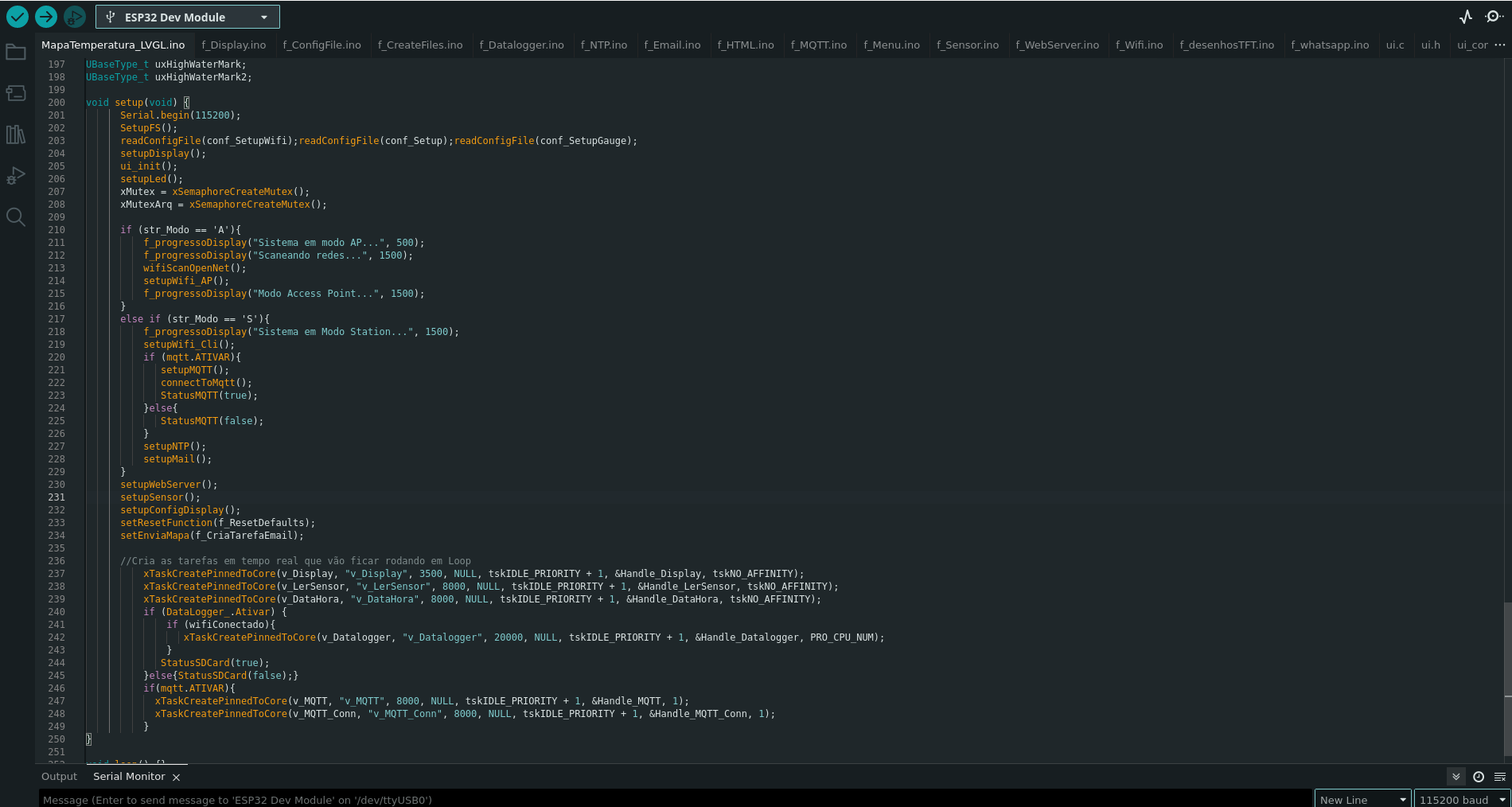
The code below is my initial program. It will call setupDisplay() which was already posted above and setupSDCard() which was also posted above, and also indicates the libraries I am using.
I’m making a mistake and I don’t know where it is
extern "C"{
      #include "freertos/FreeRTOS.h"
      #include <freertos/task.h>
      #include "freertos/timers.h"
}

//Bibliotecas usadas no Projeto:
      #include <WiFi.h>
      #include <WiFiUdp.h>
      #include <ArduinoJson.h>
      #include <SPIFFS.h>
      #include <AsyncWebServer_WT32_ETH01.h>
      #include <SPI.h>
      #include <OneWire.h>
      #include <DallasTemperature.h>
      #include <ESP_Mail_Client.h>
      #include <UrlEncode.h>
      #include <AsyncMQTT_ESP32.h>
      #include <lvgl.h>
      #include <TFT_eSPI.h>
      #include "ui.h"
      #include "f_Globals.h"
      #include "SD.h"
      #include <NTPClient.h>
      #include <TimeLib.h>
      //#include <TimeAlarms.h>

// Variables usadas no setup para configurações do usuario
      //bool Run;
      char str_Modo;
      String Wifi_SSID;
      String Wifi_Pass;
      bool wifiConectado;

// Objects
      DynamicJsonDocument json(2048); //tava em 2048
      //DynamicJsonDocument oJsonRun(2048); //Tava 2048 e funcionando bem.
      JsonArray jsonArrayRun;

      #define FileFS SPIFFS
      #define FORMAT_SPIFFS_IF_FAILED true

      FS* filesystem = &SPIFFS;
      const char* conf_SetupWifi = "/conf_SetupWifi.json";
      const char* conf_Networks = "/conf_Networks.json";
      const char* conf_Setup = "/conf_Setup.json";
      const char* conf_SetupGauge = "/conf_SetupGauge.json";

//Variaveis relaciondas ao Cartão:
/*
      struct structSD {
            char Tipo[5];
            uint64_t Tam;
            uint64_t TotalSpace;
            uint64_t Uso;

      };
      structSD SD_;

*/
      const char* fileWRITE = "WRITE";
      const char* fileAPPEND = "APPEND";

      AsyncWebServer server(80); //Objeto WebServer
//Funções executadas de forma assyncrona
      void v_LerSensor(void *parameters);
      TaskHandle_t Handle_LerSensor = NULL;

      void v_Display(void *parameters);
      TaskHandle_t Handle_Display = NULL;

      void v_Datalogger(void *parameters);
      TaskHandle_t Handle_Datalogger = NULL;

      void v_EnviaEmail(void *parameters);
      TaskHandle_t Handle_EnviaEmail = NULL;

      void v_MQTT(void *parameters);
      TaskHandle_t Handle_MQTT = NULL;

      void v_MQTT_Conn(void *parameters);
      TaskHandle_t Handle_MQTT_Conn = NULL;

      void v_VerificaWifi(void *parameters);
      TaskHandle_t Handle_VerificaWifi = NULL;

      void v_ApagarLog(void *parameters);
      TaskHandle_t Handle_ApagarLog = NULL;

      void v_DataHora(void *parameters);
      TaskHandle_t Handle_DataHora = NULL;

      void v_CreateFiles(void *parameters);
      TaskHandle_t Handle_CreateFiles = NULL;

      void v_AlarmeEnviado(void *pvParameters);

      SemaphoreHandle_t xMutex;
      SemaphoreHandle_t xMutexArq;

//Objetos usados no sensor de temperatura
      OneWire oneWire(22);
      DallasTemperature DS18B20(&oneWire);
      float tempC;
      float tempF;
      char tempC_char[20];


//Variaveis do Datalogger
      struct structDataLogger {
            int Intervalo;
            char * NomeArq;
            bool Ativar;
            int8_t Retencao;
            String HoraEnvio;
            bool AlarmeEnviado;
      };
      structDataLogger DataLogger_;

//Variaveis e objetos do NTP
      struct structNTP {
            int FusoHorario;
            String Servidor;
            int Intervalo;
      };
      structNTP ntp_;

      WiFiUDP udp;
      String ServidorNTP;
      NTPClient ntp(udp);
      struct tm data;
      int hora;
      char data_formatadaX[11];
      char datahora_formatadaX[64];
      String hora_ntp;

//Variaveis do MQTT
      struct structMQTT {
            IPAddress HOST;
            int PORT;
            String USER;
            String PASS;
            String TOPIC;
            bool ATIVAR;
            int Intervalo;
      };
      structMQTT mqtt;

      AsyncMqttClient mqttClient;
      TimerHandle_t mqttReconnectTimer;
      unsigned int tempo;
      long lastReconnectAttempt = 0;

//Váriaveis do Email
      struct structMailHost {
            bool Ativar;
            String Host;
            int Port;
            String Autor_Nome;
            String Autor_Email;
            String Autor_Senha;
            String Dest_Nome;
            String Dest_Email;
            String Assunto;
            int Prioridade;
      };
      structMailHost mail;

      SMTPSession smtp;
      void smtpCallback(SMTP_Status status);
      bool enviaEmail_TXT(String nomeRemetente,
                          String emailRemetente,
                          String senhaRemetente,
                          String assunto,
                          String nomeDestinatario,
                          String emailDestinatario,
                          String messageTXT,
                          String stmpHost,
                          int stmpPort,
                          int Prioridade
                          );
//Variaveis usadas no Display
      static const uint16_t screenWidth  = 240;
      static const uint16_t screenHeight = 320;
      uint16_t calData[5] = { 348, 3333, 264, 3358, 2 };
      TFT_eSPI lcd = TFT_eSPI(); /* TFT entity */
      static lv_disp_draw_buf_t draw_buf;
      static lv_color_t buf1[ screenWidth * screenHeight / 13 ];
      //Usada no f_refreshScreen()
      unsigned long pMillis_2 = 0;
      const long inter_2 = 10;
//Led's
      int Led1 = 17;
      int Led2 = 4;
      int Led3 = 16;

UBaseType_t uxHighWaterMark;
UBaseType_t uxHighWaterMark2;

void setup(void) {
      Serial.begin(115200);
      SetupFS();
      readConfigFile(conf_SetupWifi);readConfigFile(conf_Setup);readConfigFile(conf_SetupGauge);
      setupDisplay();
      ui_init();
      setupLed();
      xMutex = xSemaphoreCreateMutex();
      xMutexArq = xSemaphoreCreateMutex();

      if (str_Modo == 'A'){
          f_progressoDisplay("Sistema em modo AP...", 500);
          f_progressoDisplay("Scaneando redes...", 1500);
          wifiScanOpenNet();
          setupWifi_AP();
          f_progressoDisplay("Modo Access Point...", 1500);
      }
      else if (str_Modo == 'S'){
          f_progressoDisplay("Sistema em Modo Station...", 1500);
          setupWifi_Cli();
          if (mqtt.ATIVAR){
             setupMQTT();
             connectToMqtt();
             StatusMQTT(true);
          }else{
             StatusMQTT(false);
          }
          setupNTP();
          setupMail();
      }
      setupWebServer();
      setupSensor();
      setupConfigDisplay();
      setResetFunction(f_ResetDefaults);
      setEnviaMapa(f_CriaTarefaEmail);

      //Cria as tarefas em tempo real que vão ficar rodando em Loop
          xTaskCreatePinnedToCore(v_Display, "v_Display", 3500, NULL, tskIDLE_PRIORITY + 1, &Handle_Display, tskNO_AFFINITY);
          xTaskCreatePinnedToCore(v_LerSensor, "v_LerSensor", 8000, NULL, tskIDLE_PRIORITY + 1, &Handle_LerSensor, tskNO_AFFINITY);
          xTaskCreatePinnedToCore(v_DataHora, "v_DataHora", 8000, NULL, tskIDLE_PRIORITY + 1, &Handle_DataHora, tskNO_AFFINITY);
          if (DataLogger_.Ativar) {
              if (wifiConectado){
                 xTaskCreatePinnedToCore(v_Datalogger, "v_Datalogger", 20000, NULL, tskIDLE_PRIORITY + 1, &Handle_Datalogger, PRO_CPU_NUM);
              }
             StatusSDCard(true);
          }else{StatusSDCard(false);}
          if(mqtt.ATIVAR){
            xTaskCreatePinnedToCore(v_MQTT, "v_MQTT", 8000, NULL, tskIDLE_PRIORITY + 1, &Handle_MQTT, 1);
            xTaskCreatePinnedToCore(v_MQTT_Conn, "v_MQTT_Conn", 8000, NULL, tskIDLE_PRIORITY + 1, &Handle_MQTT_Conn, 1);
          }
}

void loop() {}
OK this is what I believe is going on.
So the skinny is it looks like TFT_eSPI only does SPI touch drivers that are on the same bus as an SPI LCD display. I looked at the code for the SD library in espressif’s SDK for the arduino library and it uses the SPI library in the same SDK. The SPI library defaults to a host of HSPI. The TFT_eSPI library defaults to using the VSPI host. So you are trying to use the same sets of pins for 2 different SPI hosts and that is why you are having problems. I believe if you set the macro USE_HSPI_PORT that should fix your issue. You didn’t post the setup code for TFT_eSPI so I have no way of knowing how it is configured.
Thank you very much again for your help.
The TFT_eSPI library code is User_Setup.h
//                            USER DEFINED SETTINGS
//   Set driver type, fonts to be loaded, pins used and SPI control method etc
//
//   See the User_Setup_Select.h file if you wish to be able to define multiple
//   setups and then easily select which setup file is used by the compiler.
//
//   If this file is edited correctly then all the library example sketches should
//   run without the need to make any more changes for a particular hardware setup!
//   Note that some sketches are designed for a particular TFT pixel width/height


// ##################################################################################
//
// Section 1. Call up the right driver file and any options for it
//
// ##################################################################################

// Define STM32 to invoke optimised processor support (only for STM32)
//#define STM32

// Defining the STM32 board allows the library to optimise the performance
// for UNO compatible "MCUfriend" style shields
//#define NUCLEO_64_TFT
//#define NUCLEO_144_TFT

// STM32 8 bit parallel only:
// If STN32 Port A or B pins 0-7 are used for 8 bit parallel data bus bits 0-7
// then this will improve rendering performance by a factor of ~8x
//#define STM_PORTA_DATA_BUS
//#define STM_PORTB_DATA_BUS

// Tell the library to use 8 bit parallel mode (otherwise SPI is assumed)
//#define TFT_PARALLEL_8_BIT

// Display type -  only define if RPi display
//#define RPI_DISPLAY_TYPE // 20MHz maximum SPI

// Only define one driver, the other ones must be commented out
//#define ILI9341_DRIVER       // Generic driver for common displays
#define ILI9341_2_DRIVER     // Alternative ILI9341 driver, see https://github.com/Bodmer/TFT_eSPI/issues/1172
//#define ST7735_DRIVER      // Define additional parameters below for this display
//#define ILI9163_DRIVER     // Define additional parameters below for this display
//#define S6D02A1_DRIVER
//#define RPI_ILI9486_DRIVER // 20MHz maximum SPI
//#define HX8357D_DRIVER
//#define ILI9481_DRIVER
//#define ILI9486_DRIVER
//#define ILI9488_DRIVER     // WARNING: Do not connect ILI9488 display SDO to MISO if other devices share the SPI bus (TFT SDO does NOT tristate when CS is high)
//#define ST7789_DRIVER      // Full configuration option, define additional parameters below for this display
//#define ST7789_2_DRIVER    // Minimal configuration option, define additional parameters below for this display
//#define R61581_DRIVER
//#define RM68140_DRIVER
//#define ST7796_DRIVER
//#define SSD1351_DRIVER
//#define SSD1963_480_DRIVER
//#define SSD1963_800_DRIVER
//#define SSD1963_800ALT_DRIVER
//#define ILI9225_DRIVER
//#define GC9A01_DRIVER

// Some displays support SPI reads via the MISO pin, other displays have a single
// bi-directional SDA pin and the library will try to read this via the MOSI line.
// To use the SDA line for reading data from the TFT uncomment the following line:

// #define TFT_SDA_READ      // This option is for ESP32 ONLY, tested with ST7789 and GC9A01 display only

// For ST7735, ST7789 and ILI9341 ONLY, define the colour order IF the blue and red are swapped on your display
// Try ONE option at a time to find the correct colour order for your display

//  #define TFT_RGB_ORDER TFT_RGB  // Colour order Red-Green-Blue
//  #define TFT_RGB_ORDER TFT_BGR  // Colour order Blue-Green-Red

// For M5Stack ESP32 module with integrated ILI9341 display ONLY, remove // in line below

// #define M5STACK

// For ST7789, ST7735, ILI9163 and GC9A01 ONLY, define the pixel width and height in portrait orientation
// #define TFT_WIDTH  80
// #define TFT_WIDTH  128
// #define TFT_WIDTH  128 // ST7789 240 x 240 and 240 x 320
#define TFT_WIDTH  240
// #define TFT_WIDTH  320
// #define TFT_HEIGHT 160
// #define TFT_HEIGHT 128
//#define TFT_HEIGHT 160 // ST7789 240 x 240
#define TFT_HEIGHT 320 // ST7789 240 x 320
// #define TFT_HEIGHT 240 // GC9A01 240 x 240 //#define TFT_HEIGHT 480
//#define TFT_HEIGHT 480 //

// For ST7735 ONLY, define the type of display, originally this was based on the
// colour of the tab on the screen protector film but this is not always true, so try
// out the different options below if the screen does not display graphics correctly,
// e.g. colours wrong, mirror images, or stray pixels at the edges.
// Comment out ALL BUT ONE of these options for a ST7735 display driver, save this
// this User_Setup file, then rebuild and upload the sketch to the board again:

// #define ST7735_INITB
// #define ST7735_GREENTAB
// #define ST7735_GREENTAB2
// #define ST7735_GREENTAB3
// #define ST7735_GREENTAB128    // For 128 x 128 display
// #define ST7735_GREENTAB160x80 // For 160 x 80 display (BGR, inverted, 26 offset)
// #define ST7735_REDTAB
// #define ST7735_BLACKTAB
// #define ST7735_REDTAB160x80   // For 160 x 80 display with 24 pixel offset

// If colours are inverted (white shows as black) then uncomment one of the next
// 2 lines try both options, one of the options should correct the inversion.

// #define TFT_INVERSION_ON
// #define TFT_INVERSION_OFF


// ##################################################################################
//
// Section 2. Define the pins that are used to interface with the display here
//
// ##################################################################################

// If a backlight control signal is available then define the TFT_BL pin in Section 2
// below. The backlight will be turned ON when tft.begin() is called, but the library
// needs to know if the LEDs are ON with the pin HIGH or LOW. If the LEDs are to be
// driven with a PWM signal or turned OFF/ON then this must be handled by the user
// sketch. e.g. with digitalWrite(TFT_BL, LOW);

#define TFT_BL   27            // LED back-light control pin
#define TFT_BACKLIGHT_ON HIGH  // Level to turn ON back-light (HIGH or LOW)


// We must use hardware SPI, a minimum of 3 GPIO pins is needed.
// Typical setup for ESP8266 NodeMCU ESP-12 is :
//
// Display SDO/MISO  to NodeMCU pin D6 (or leave disconnected if not reading TFT)
// Display LED       to NodeMCU pin VIN (or 5V, see below)
// Display SCK       to NodeMCU pin D5
// Display SDI/MOSI  to NodeMCU pin D7
// Display DC (RS/AO)to NodeMCU pin D3
// Display RESET     to NodeMCU pin D4 (or RST, see below)
// Display CS        to NodeMCU pin D8 (or GND, see below)
// Display GND       to NodeMCU pin GND (0V)
// Display VCC       to NodeMCU 5V or 3.3V
//
// The TFT RESET pin can be connected to the NodeMCU RST pin or 3.3V to free up a control pin
//
// The DC (Data Command) pin may be labelled AO or RS (Register Select)
//
// With some displays such as the ILI9341 the TFT CS pin can be connected to GND if no more
// SPI devices (e.g. an SD Card) are connected, in this case comment out the #define TFT_CS
// line below so it is NOT defined. Other displays such at the ST7735 require the TFT CS pin
// to be toggled during setup, so in these cases the TFT_CS line must be defined and connected.
//
// The NodeMCU D0 pin can be used for RST
//
//
// Note: only some versions of the NodeMCU provide the USB 5V on the VIN pin
// If 5V is not available at a pin you can use 3.3V but backlight brightness
// will be lower.


// ###### EDIT THE PIN NUMBERS IN THE LINES FOLLOWING TO SUIT YOUR ESP8266 SETUP ######

// For NodeMCU - use pin numbers in the form PIN_Dx where Dx is the NodeMCU pin designation
//#define TFT_CS   PIN_D8  // Chip select control pin D8
//#define TFT_DC   PIN_D3  // Data Command control pin
//#define TFT_RST  PIN_D4  // Reset pin (could connect to NodeMCU RST, see next line)
//#define TFT_RST  -1    // Set TFT_RST to -1 if the display RESET is connected to NodeMCU RST or 3.3V

//#define TFT_BL PIN_D1  // LED back-light (only for ST7789 with backlight control pin)

//#define TOUCH_CS PIN_D2     // Chip select pin (T_CS) of touch screen

//#define TFT_WR PIN_D2       // Write strobe for modified Raspberry Pi TFT only


// ######  FOR ESP8266 OVERLAP MODE EDIT THE PIN NUMBERS IN THE FOLLOWING LINES  ######

// Overlap mode shares the ESP8266 FLASH SPI bus with the TFT so has a performance impact
// but saves pins for other functions. It is best not to connect MISO as some displays
// do not tristate that line when chip select is high!
// On NodeMCU 1.0 SD0=MISO, SD1=MOSI, CLK=SCLK to connect to TFT in overlap mode
// On NodeMCU V3  S0 =MISO, S1 =MOSI, S2 =SCLK
// In ESP8266 overlap mode the following must be defined

//#define TFT_SPI_OVERLAP

// In ESP8266 overlap mode the TFT chip select MUST connect to pin D3
//#define TFT_CS   PIN_D3
//#define TFT_DC   PIN_D5  // Data Command control pin
//#define TFT_RST  PIN_D4  // Reset pin (could connect to NodeMCU RST, see next line)
//#define TFT_RST  -1  // Set TFT_RST to -1 if the display RESET is connected to NodeMCU RST or 3.3V


// ###### EDIT THE PIN NUMBERS IN THE LINES FOLLOWING TO SUIT YOUR ESP32 SETUP   ######

// For ESP32 Dev board (only tested with ILI9341 display)
// The hardware SPI can be mapped to any pins

// #define TFT_MISO -1
// #define TFT_MOSI 14
// #define TFT_SCLK 33
// #define TFT_CS   -1  // Chip select control pin
// #define TFT_DC    13  // Data Command control pin
// #define TFT_RST   12  // Reset pin (could connect to RST pin)
//#define TFT_RST  -1  // Set TFT_RST to -1 if display RESET is connected to ESP32 board RST

// For ESP32 Dev board (only tested with GC9A01 display)
// The hardware SPI can be mapped to any pins
#define ESP32_DMA
#define TFT_MISO 12
#define TFT_MOSI 13 // In some display driver board, it might be written as "SDA" and so on.
#define TFT_SCLK 14
#define TFT_CS   15  // Chip select control pin
#define TFT_DC   2  // Data Command control pin
#define TFT_RST  -1  // Reset pin (could connect to Arduino RESET pin)
#define TFT_BL   27  // LED back-light

#define TOUCH_CS 33     // Chip select pin (T_CS) of touch screen

//#define TFT_WR 22    // Write strobe for modified Raspberry Pi TFT only

// For the M5Stack module use these #define lines
//#define TFT_MISO 19
//#define TFT_MOSI 23
//#define TFT_SCLK 18
//#define TFT_CS   14  // Chip select control pin
//#define TFT_DC   27  // Data Command control pin
//#define TFT_RST  33  // Reset pin (could connect to Arduino RESET pin)
//#define TFT_BL   32  // LED back-light (required for M5Stack)

// ######       EDIT THE PINs BELOW TO SUIT YOUR ESP32 PARALLEL TFT SETUP        ######

// The library supports 8 bit parallel TFTs with the ESP32, the pin
// selection below is compatible with ESP32 boards in UNO format.
// Wemos D32 boards need to be modified, see diagram in Tools folder.
// Only ILI9481 and ILI9341 based displays have been tested!

// Parallel bus is only supported for the STM32 and ESP32
// Example below is for ESP32 Parallel interface with UNO displays

// Tell the library to use 8 bit parallel mode (otherwise SPI is assumed)
//#define TFT_PARALLEL_8_BIT

// The ESP32 and TFT the pins used for testing are:
//#define TFT_CS   33  // Chip select control pin (library pulls permanently low
//#define TFT_DC   15  // Data Command control pin - must use a pin in the range 0-31
//#define TFT_RST  32  // Reset pin, toggles on startup

//#define TFT_WR    4  // Write strobe control pin - must use a pin in the range 0-31
//#define TFT_RD    2  // Read strobe control pin

//#define TFT_D0   12  // Must use pins in the range 0-31 for the data bus
//#define TFT_D1   13  // so a single register write sets/clears all bits.
//#define TFT_D2   26  // Pins can be randomly assigned, this does not affect
//#define TFT_D3   25  // TFT screen update performance.
//#define TFT_D4   17
//#define TFT_D5   16
//#define TFT_D6   27
//#define TFT_D7   14

// ######       EDIT THE PINs BELOW TO SUIT YOUR STM32 SPI TFT SETUP        ######

// The TFT can be connected to SPI port 1 or 2
//#define TFT_SPI_PORT 1 // SPI port 1 maximum clock rate is 55MHz
//#define TFT_MOSI PA7
//#define TFT_MISO PA6
//#define TFT_SCLK PA5

//#define TFT_SPI_PORT 2 // SPI port 2 maximum clock rate is 27MHz
//#define TFT_MOSI PB15
//#define TFT_MISO PB14
//#define TFT_SCLK PB13

// Can use Ardiuno pin references, arbitrary allocation, TFT_eSPI controls chip select
//#define TFT_CS   D5 // Chip select control pin to TFT CS
//#define TFT_DC   D6 // Data Command control pin to TFT DC (may be labelled RS = Register Select)
//#define TFT_RST  D7 // Reset pin to TFT RST (or RESET)
// OR alternatively, we can use STM32 port reference names PXnn
//#define TFT_CS   PE11 // Nucleo-F767ZI equivalent of D5
//#define TFT_DC   PE9  // Nucleo-F767ZI equivalent of D6
//#define TFT_RST  PF13 // Nucleo-F767ZI equivalent of D7

//#define TFT_RST  -1   // Set TFT_RST to -1 if the display RESET is connected to processor reset
                        // Use an Arduino pin for initial testing as connecting to processor reset
                        // may not work (pulse too short at power up?)

// ##################################################################################
//
// Section 3. Define the fonts that are to be used here
//
// ##################################################################################

// Comment out the #defines below with // to stop that font being loaded
// The ESP8366 and ESP32 have plenty of memory so commenting out fonts is not
// normally necessary. If all fonts are loaded the extra FLASH space required is
// about 17Kbytes. To save FLASH space only enable the fonts you need!

#define LOAD_GLCD   // Font 1. Original Adafruit 8 pixel font needs ~1820 bytes in FLASH
#define LOAD_FONT2  // Font 2. Small 16 pixel high font, needs ~3534 bytes in FLASH, 96 characters
#define LOAD_FONT4  // Font 4. Medium 26 pixel high font, needs ~5848 bytes in FLASH, 96 characters
#define LOAD_FONT6  // Font 6. Large 48 pixel font, needs ~2666 bytes in FLASH, only characters 1234567890:-.apm
#define LOAD_FONT7  // Font 7. 7 segment 48 pixel font, needs ~2438 bytes in FLASH, only characters 1234567890:-.
#define LOAD_FONT8  // Font 8. Large 75 pixel font needs ~3256 bytes in FLASH, only characters 1234567890:-.
//#define LOAD_FONT8N // Font 8. Alternative to Font 8 above, slightly narrower, so 3 digits fit a 160 pixel TFT
#define LOAD_GFXFF  // FreeFonts. Include access to the 48 Adafruit_GFX free fonts FF1 to FF48 and custom fonts

// Comment out the #define below to stop the SPIFFS filing system and smooth font code being loaded
// this will save ~20kbytes of FLASH
#define SMOOTH_FONT


// ##################################################################################
//
// Section 4. Other options
//
// ##################################################################################

// Define the SPI clock frequency, this affects the graphics rendering speed. Too
// fast and the TFT driver will not keep up and display corruption appears.
// With an ILI9341 display 40MHz works OK, 80MHz sometimes fails
// With a ST7735 display more than 27MHz may not work (spurious pixels and lines)
// With an ILI9163 display 27 MHz works OK.

// #define SPI_FREQUENCY   1000000
// #define SPI_FREQUENCY   5000000
//#define SPI_FREQUENCY  10000000
//#define SPI_FREQUENCY  20000000
//#define SPI_FREQUENCY  27000000
//#define SPI_FREQUENCY  40000000
#define SPI_FREQUENCY  55000000 // STM32 SPI1 only (SPI2 maximum is 27MHz)
//#define SPI_FREQUENCY  65000000
//#define SPI_FREQUENCY  80000000

// Optional reduced SPI frequency for reading TFT
#define SPI_READ_FREQUENCY  20000000

// The XPT2046 requires a lower SPI clock rate of 2.5MHz so we define that here:
 #define SPI_TOUCH_FREQUENCY  2500000  //2500000

// The ESP32 has 2 free SPI ports i.e. VSPI and HSPI, the VSPI is the default.
// If the VSPI port is in use and pins are not accessible (e.g. TTGO T-Beam)
// then uncomment the following line:
//#define USE_HSPI_PORT

// Comment out the following #define if "SPI Transactions" do not need to be
// supported. When commented out the code size will be smaller and sketches will
// run slightly faster, so leave it commented out unless you need it!

// Transaction support is needed to work with SD library but not needed with TFT_SdFat
// Transaction support is required if other SPI devices are connected.

// Transactions are automatically enabled by the library for an ESP32 (to use HAL mutex)
// so changing it here has no effect

// #define SUPPORT_TRANSACTIONS
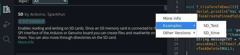
SD.zip (149.7 KB)
I took advantage and attached it to the SD Card library I’m using.
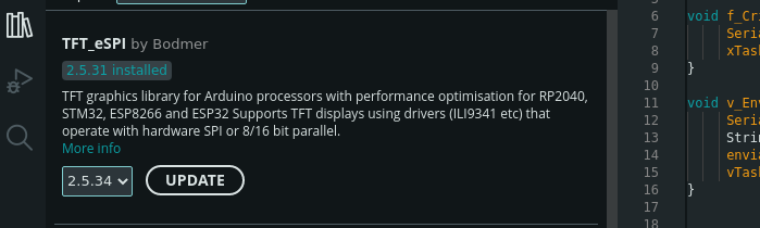
I didn’t add the TFT_eSPI library because the zip file was too big.
And I also attached images of the versions I’m using.
How can I enable this USE_HSPI_PORT ?
before you include TFT_eSPI you want to add the line
#define USE_HSPI_PORT 1
I try, I’ll send you the result later.
I am hoping that will get it done the touch IC isn’t exactly SPI it is some other type of coms that shares the same pins as the SPI for the display. I am going to look at the schematic again and see if the SDCard reader is also on the same bus.