Instead of manually searching the code, why don’t you just set a watchpoint to trigger once the corruption happens?
That would stop the debugger exactly where you want.
The watchpoint doesn’t get hit. Perhaps that is no surprise since the elf.map shows the FLASH region as xr - ReadOnly. I haven’t looked into how the flash is actually written, but it looks like it doesn’t trigger the RP2040 hardware debug unit. Either that, or the Eclipse debug front end doesn’t set the watchpoint properly.
However, armed with what I discovered already I found the problem; It lies in the flash size specified in ports/rp2/boards/mpconfigboard.h.
Reducing MICROPY_HW_FLASH_STORAGE_BYTES from 1408 kB to 1024 should leave enough headroom for varying build sizes of lvgl, but this will require continued vigilance from the developer as they incorporate the lvgl and uPy features they require. I suggest a comment in that file, plus something prominent in the documentation, maybe rp2 port specific or more generic if it is thought this is a setting that can cause issues more generally (this does not look RP2040 or Pico specific to me).
Please let me know if you’d like me to make a pull request.
We’ll be very happy with a PR that advertises your findings!
One more very useful PR could be a display driver. The RP2 port is the only port that does not come with any display driver.
You mentioned you have a working display driver - that could be very useful for others too.
What is your PR process? Do I need permissions to make branches? I haven’t tried.
I also now have a pure python resistive touch screen driver for this display, MAR3501 (480x320 parallel with ili9486 display driver and resistive touch multiplexed on D0, D1, RS and CS). Let me know if you would like that too.
Example link to display:
This display is also easily modified to provide PWM brightness control if anyone is interested in doing that.
You don’t need any special permissions to contribute.
On GitHub when you want to contribute to a project you first fork it, commit your changes to your fork and push it.
Then you use your fork to open a Pull Request to the original repository, which is the GitHub way of proposing changes.
In our case, most drivers are under “driver” on lv_binding_micropython repo. You can create a new directory there for rp2 and add your drivers under it. If the drivers are generic and not specific to rp2, they can go under “generic” instead.
As long as it’s useful for others, we welcome any driver!
@eudoxos Looks good. The drivers I’m working on will complement these nicely, since I am targeting a display with an 8 bit parallel interface and resistive touch.
So the delay in creating a PR for my work is a combination of day job and the bit banged display driver not performing that great. Sooo…
I went ahead and implemented a RP2040 PIO state machine based 8 bit interface for the ILI9486. This handles CS, RS and WR pins and seems to run fine up to the theoretical limit of the controller, which is 66 ns write cycle, or 15 Mbytes per second, or about 50 frames a second for 320 x 480 at 16 bit colour. The state machine is hooked up with DMA, so it achieves this with little CPU overhead, beyond the lvgl rendering time. I’ve left the bit banged code in place controlled by a #define so that it can be used for reference and on non RP2 ports, but obviously performance will not be as good. Because the DMA/PIO combination is so low on CPU overhead, a pure python version of this would perform just about as well, though again only for the RP2.
I’m about ready to make a PR, but I’d like to characterise the real world performance. Do you have lv_mpy specific performance tests, or do I need to use the mainline lvgl ones? I do see some tests, but not sure if they are for drivers or how they should be run.
One unexpected issue I am seeing is that overclocking the RP2 to 250MHz causes instability in the advanced_demo application, not yet sure why that would be, it is completely reliable at the stock clock rate. Maybe an issue with the resistive touch driver I wrote, but I currently can’t test without that. A automated standalone performance test would likely clarify the source of the problem.
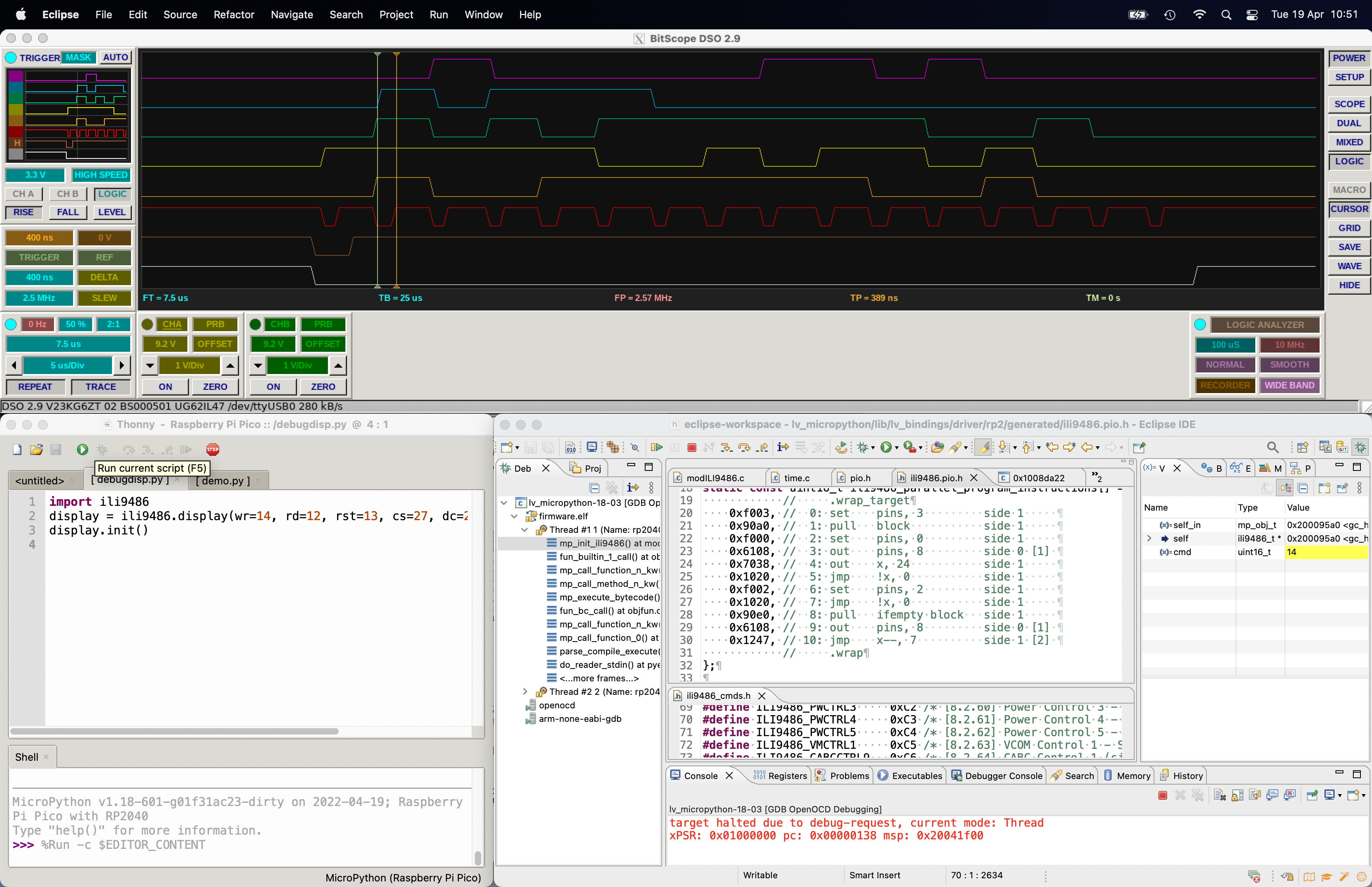
Part of initialisation sequence, slowed down to 2.5 MHz so that the scope can see it.
Bottom to top CS, RS, WR, D0->D4, all controlled by SM program lower right.